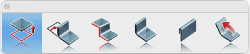
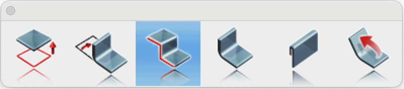
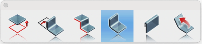
Sheet Metal tools in the application offer a comprehensive set of features for designing and editing sheet metal parts with precision and control. These tools allow users to create intricate geometries, such as tabs, bends, flanges, and hems, while preserving material integrity and adhering to key sheet metal design parameters like bend radius and k-factor. Whether designing structural components, mechanical enclosures, or decorative parts, the Sheet Metal tools simplify the entire workflow from initial design to flat pattern generation. The Sheet Metal toolset is located in the Tools menu. There are six primary Sheet Metal tools available: Tab, Bend, Contour Flange, Flange, Single Hem and Unbend.
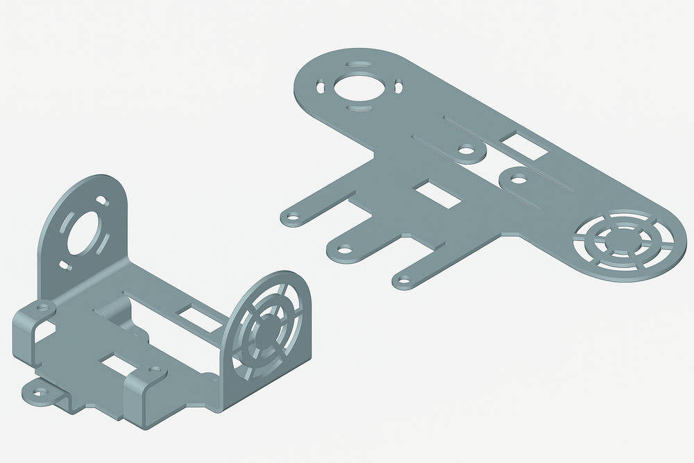
Sheet Metal Part Example
The Tab feature creates a flat, protruding extension from a sheet metal part with precision and control. A tab is typically a planar section that remains in the same plane as the base sheet or flange it extends from. It can take various shapes: rectangular, trapezoidal, or custom profiles depending on the design requirements. Tabs often serve as the foundation for additional sheet metal features, providing a starting point for operations such as bends, flanges, or cuts. This tool is essential for building the initial geometry of a sheet metal component.
Open the Sheet Metal Tools palette from the Tools menu and select the Tab tool.
Tab tool in Sheet Metal Palette
Specify the sheet metal thickness according to the design requirements.
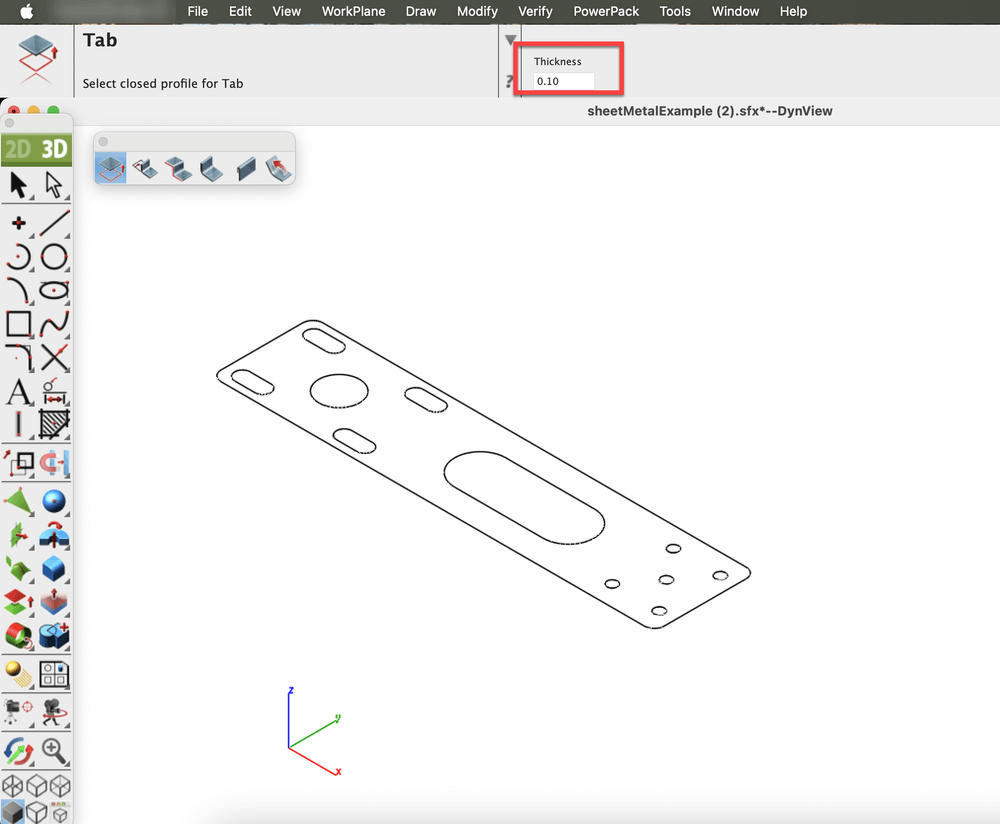
Specified the Thickness
Now select a closed profile to define the tab’s geometry. The tool automatically generates flat sheet metal section based on the defined parameters.
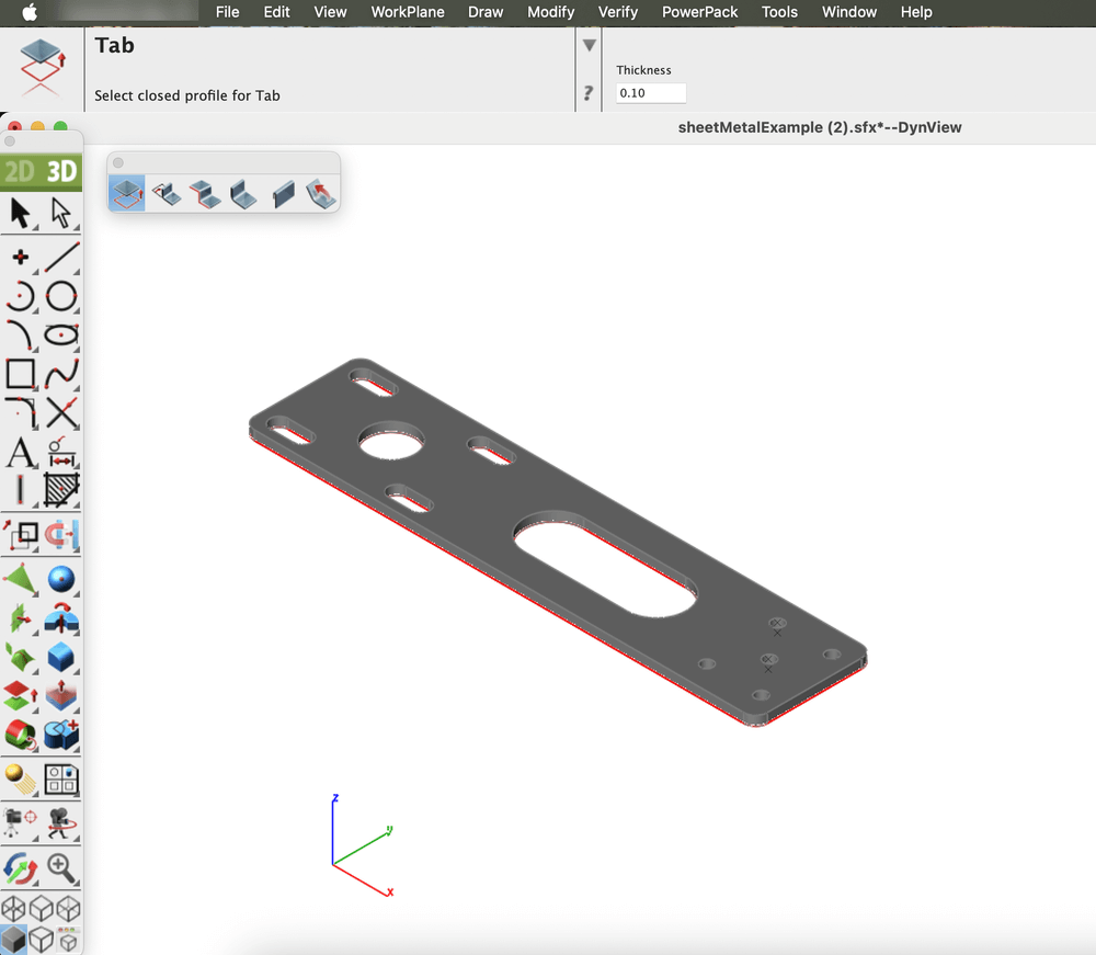
Flat sheet metal Tab generated based on defined parameters
Bend
The Bend feature is used to deform a flat sheet metal part into a curved or angled shape while maintaining material integrity. It is an essential tool for creating functional components such as brackets, enclosures, and ducts. By controlling parameters like bend angle, radius, and direction, it ensures accuracy and consistency in the design process.
Open the Sheet Metal Tools palette from the Tools menu and select the Bend tool.
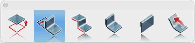
Bend tool in Sheet Metal Palette
Specify the Bend Radius and enter the desired Bend Angle.
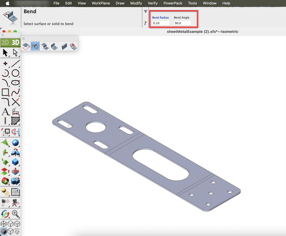
Specified the Bend Radius and Bend Angle
Select the entity and define the bend axis by selecting two points on the face to bend.
(Optional) Press the Option key to flip the bend direction.
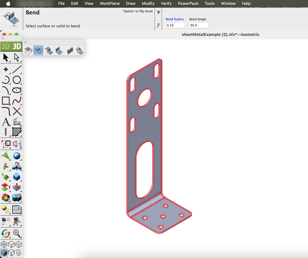
Sheet metal part after applying the Bend tool
Contour Flange
The Contour Flange feature allows the creation of a sheet metal flange by extruding a sketch profile along a defined path. The profile can include various geometric entities such as lines, arcs, splines, or elliptical arcs. Sharp corners within the profile automatically generate bends that follow the specified bend radius, ensuring smooth transitions and accurate sheet metal behavior.
Open the Sheet Metal Tools palette from the Tools menu and select the Contour Flange tool.
Contour Flange tool in Sheet Metal Palette
Draw a profile for the Contour Flange tool.
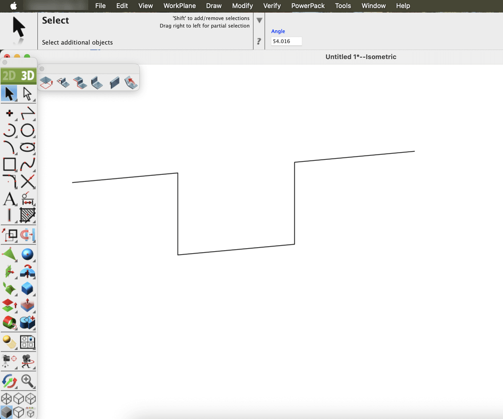
2D profile sketch created for the Contour Flange tool
Specify the Distance, Thickness, and Bend Radius in the fields displayed in the Prompt window.
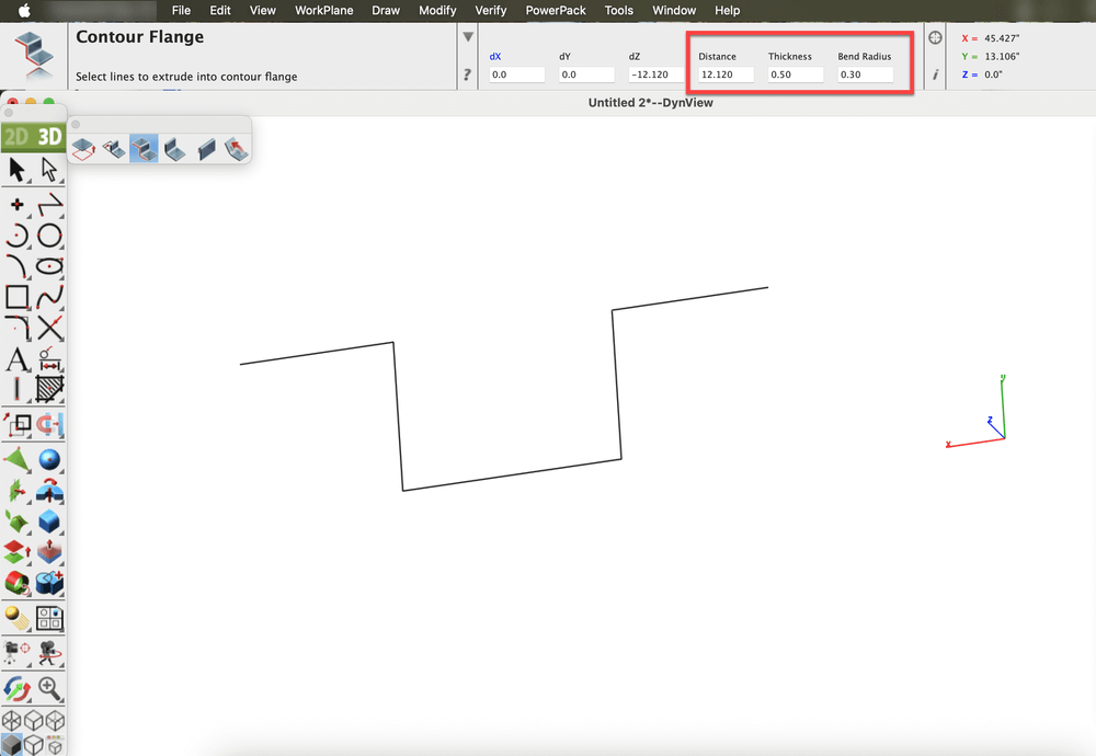
Parameters specified for Contour Flange creation
Select the drawn entity, then choose two points to define the extrusion direction for the Contour Flange.
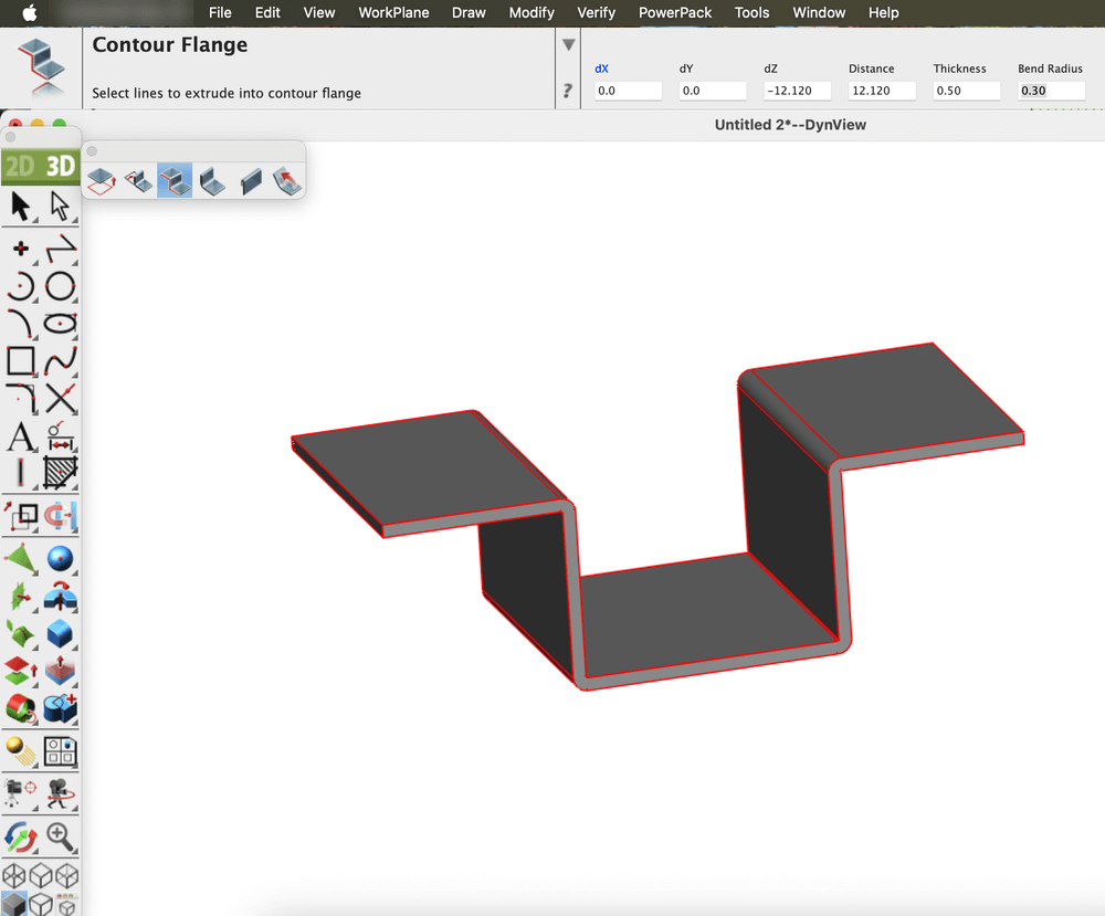
Resulting Contour Flange after applying the tool
Flange
The Flange feature adds a straight, planar extension or lip to the edge of a sheet metal part. Flanges are commonly used to strengthen components, create mounting edges, or connect adjoining parts. The tool provides precise control over key parameters such as flange length, bend angle, and bend radius, allowing for accurate and consistent results in design and manufacturing.
There are two types of flanges available:
- Full Flange: Extends along the entire length of the selected edge.
- Partial Flange: Applies only to a defined portion of the edge, offering greater design flexibility.
Open the Sheet Metal tools from the Tools menu and select the Flange Tool.
Flange tool in Sheet Metal Palette
Select the Full Edge option from the dropdown located in the Prompt window, and specify the Flange Length, Bend Radius, and Angle in the fields displayed in the Prompt window.
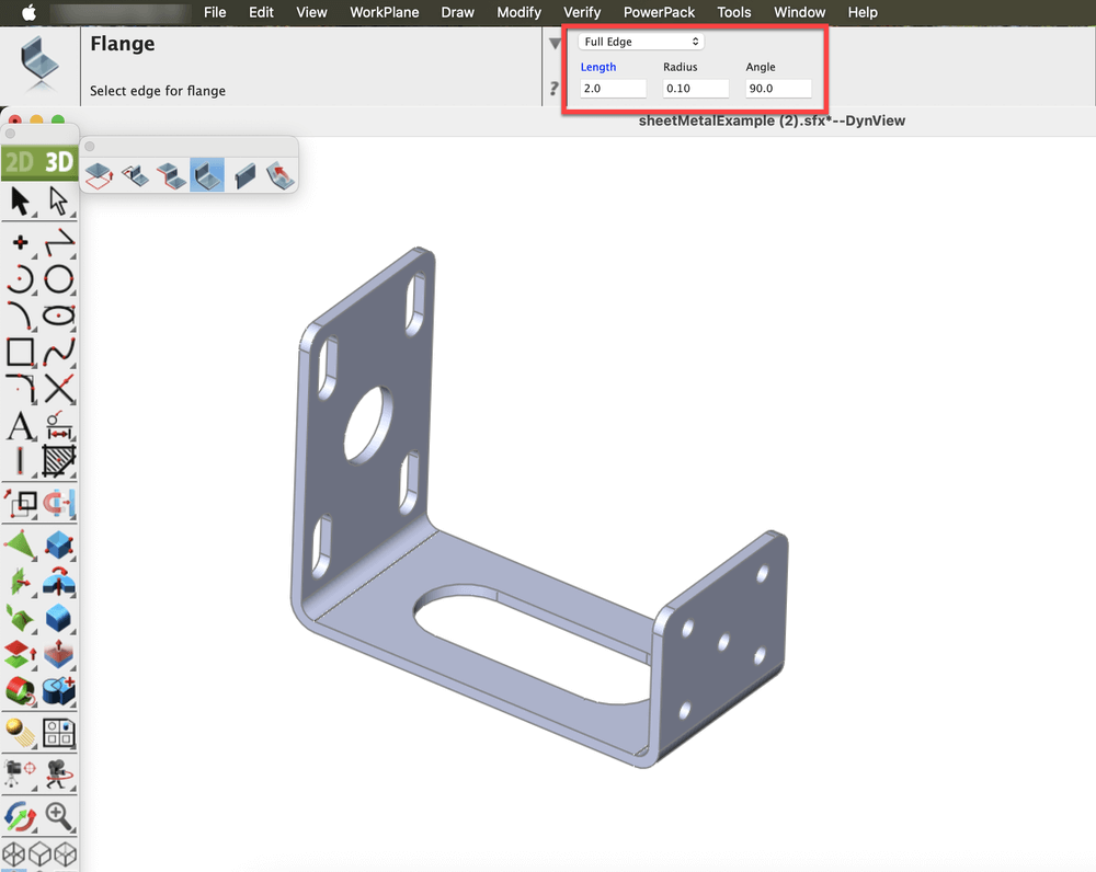
Parameters specified for Flange creation
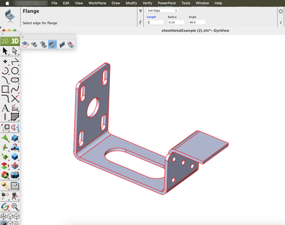
Flange (Full Edge) after applying the tool
Now select the Partial Edge option from the dropdown located in the Prompt window, and specify the Flange Length, Bend Radius, and Angle in the fields displayed in the Prompt window.
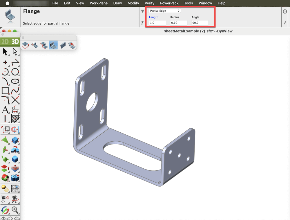
Parameters specified for Flange creation
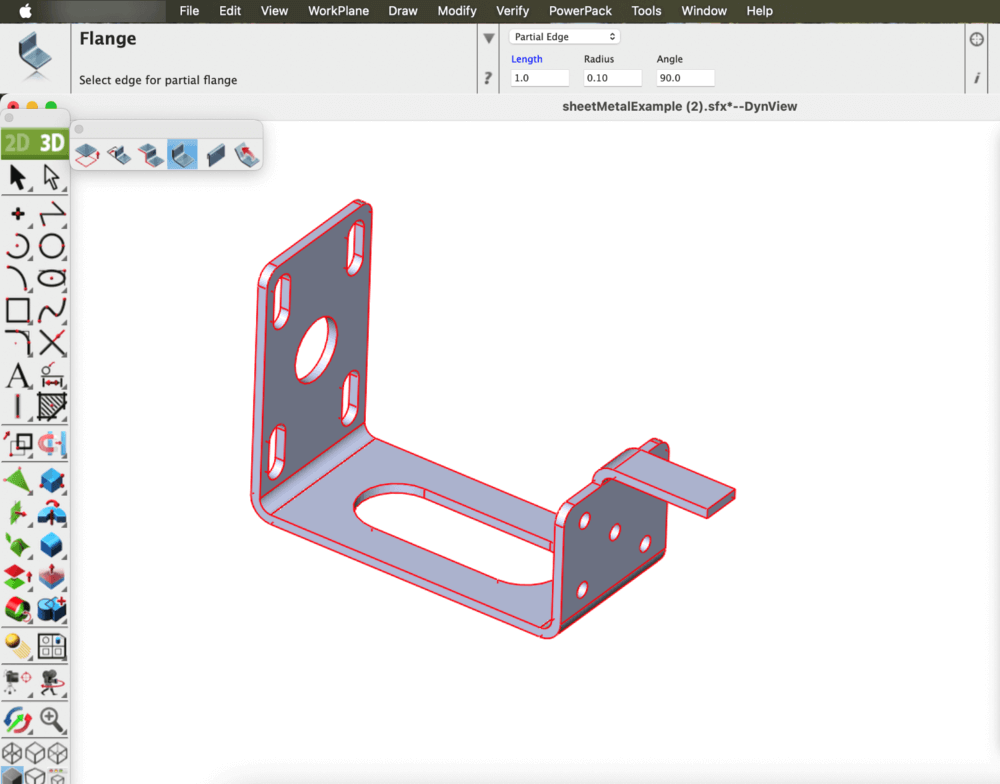
Flange (Partial Edge) after applying the tool
Single Hem
The Single Hem feature allows the edge of a sheet metal part to be folded back onto itself, forming a rounded or flattened lip. This operation enhances part strength, improves safety by eliminating sharp edges, and contributes to a cleaner appearance. Various hem types, such as teardrop, open, or closed can be applied depending on the design and functional requirements.
Open the Sheet Metal Tools palette from the Tools menu and select the Single Hem tool.
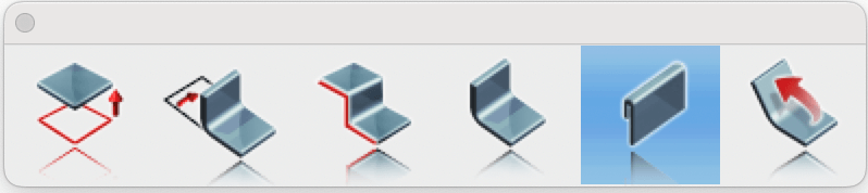
Single Hem tool in Sheet Metal Palette
Select the Straight option from the dropdown in the Prompt window, and enter the desired Length and Gap values in the corresponding fields.
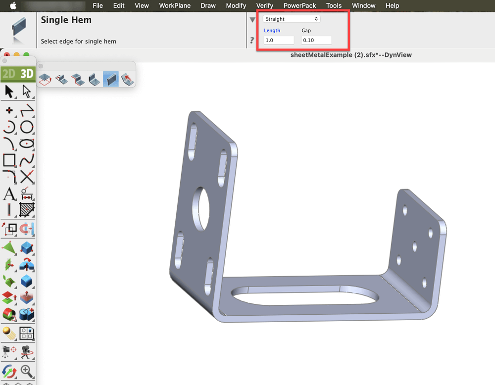
Parameters specified for Single Hem (Straight) creation
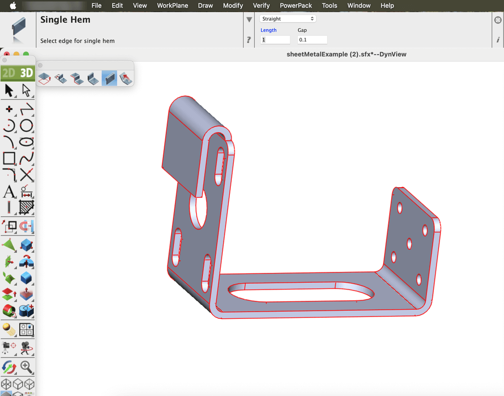
Single Hem (Straight) after applying the tool
Now select the Rolled option from the dropdown in the Prompt window, and enter the desired Radius, Angle and Thickness values in the corresponding fields.
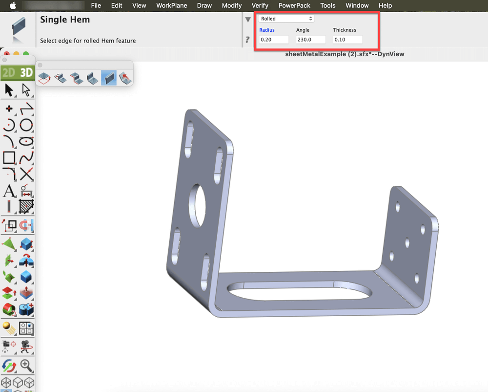
Parameters specified for Single Hem (Rolled) creation
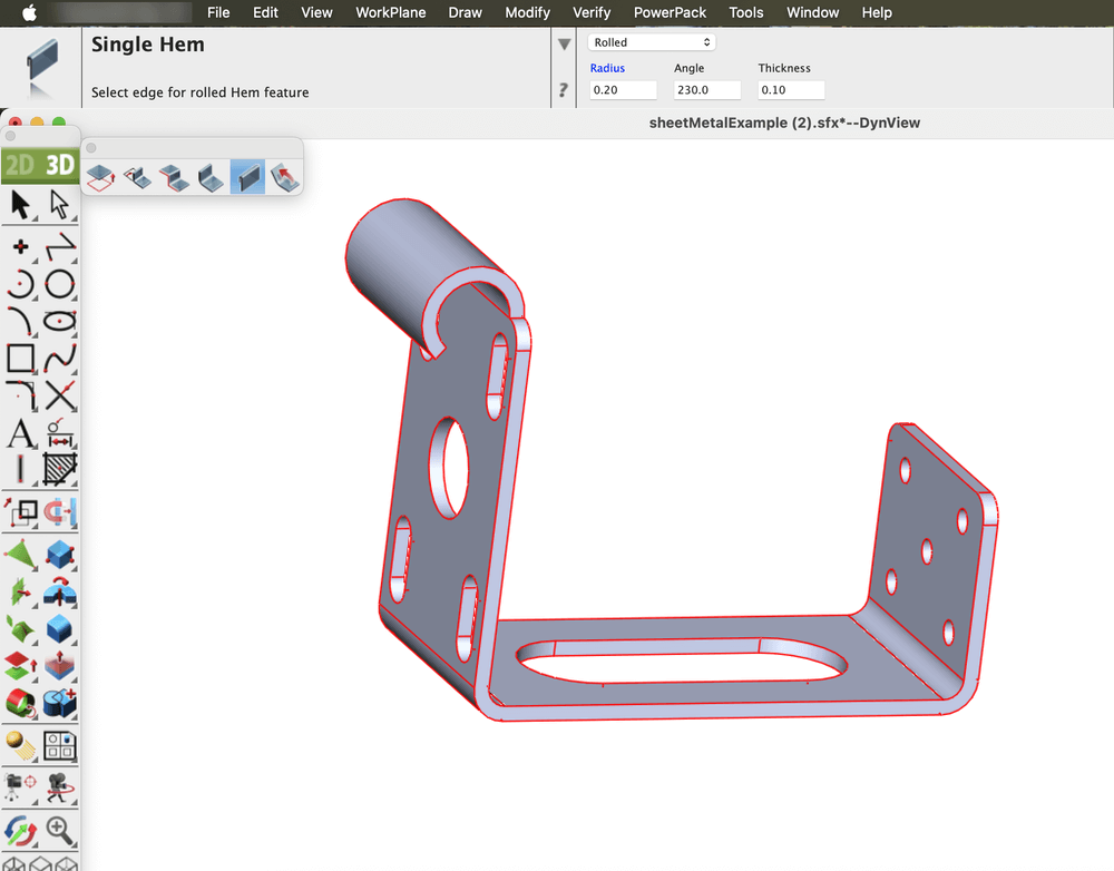
Single Hem (Rolled) after applying the tool
Unbend
The Unbend tool is used to return a bent or curved section of a sheet metal part to a flat, planar state without changing its design. It reverses the deformation by selectively flattening bends or regions while maintaining material properties and adhering to established sheet metal parameters such as bend allowance.
The K-factor is a value that represents the position of the neutral axis, the line within the sheet metal that remains unstretched and uncompressed during bending, relative to the material thickness. It is a dimensionless number, typically ranging from 0.3 to 0.5 for most materials and bend conditions, though it can vary between 0 and 1 depending on factors like material type, thickness, and bend radius. The K-factor is essential for calculating the bend allowance, which helps determine the accurate flat pattern length before bending. In practice, it ensures precise fabrication by accounting for how the material behaves during the bending process.
Open the Sheet Metal Tools palette from the Tools menu and select the Unbend tool.
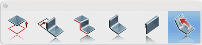
Unbend tool in Sheet Metal Palette
Set the K-Factor value for accurate unbending, and select the solid part to flatten.
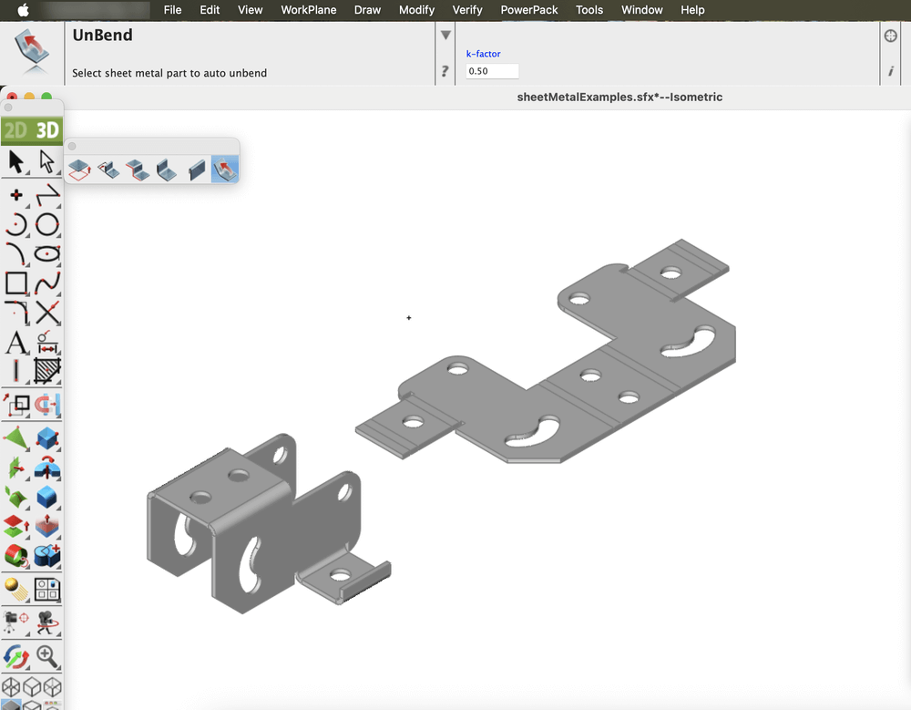
Unbend after applying the tool
The Sheet Metal tools in the application simplify the entire sheet metal design process from creating tabs and bends to applying hems and unbends. With precise control over parameters like bend radius and K-factor, these tools ensure accuracy and efficiency. They provide a seamless workflow for producing high-quality, ready-to-manufacture designs.