


Founded in 1983, IMSI is a leader in feature-rich, yet affordable, general-purpose CAD (Computer Aided Design) and home design desktop software, and a pioneer in mobile solutions for the AEC (Architectural, Engineering, and Construction) industry.

Turning My Living Room into an Elegant Dream Space (Mac)
- IMSI Store
- Blog
Redesigning a living space is more than just changing furniture or colors - it is about creating an environment that feels elegant, attractive, and welcoming at the same time. With the right balance of colors, lighting, textures, and decor, any room can be transformed into a space that reflects style, comfort, and personality. Small, thoughtful design choices often make the biggest impact, proving that elegance does not always require a large budget. A well-designed living space not only enhances the beauty of a home but also improves the way people relax, connect, and enjoy everyday moments.
In a living space, there are many elements to consider, such as the sofa, table, curtains, door and window designs, carpet, wall decor accessories, modular media storage, and floor lighting. Choosing the right items for your living room can make it look more attractive and well-designed.
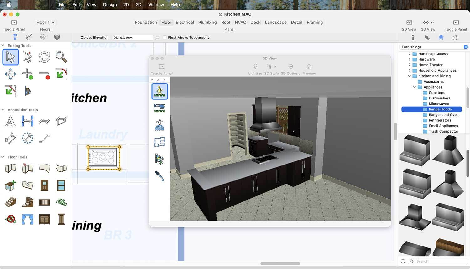
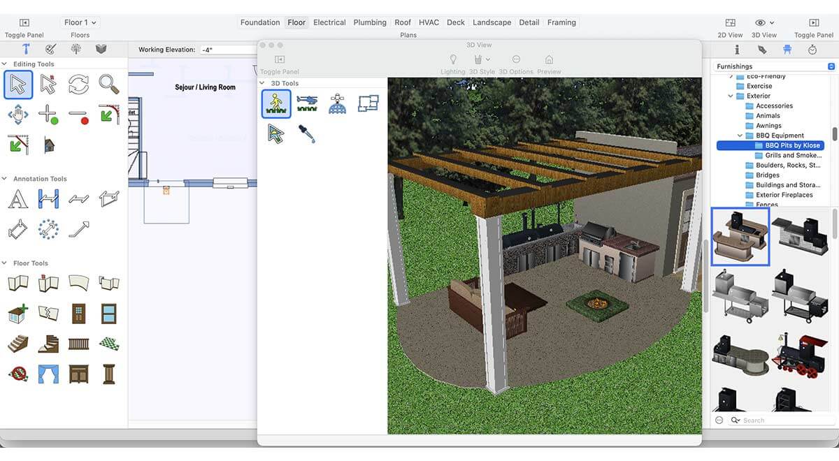
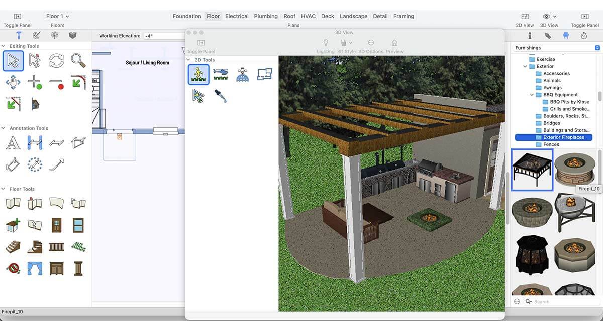
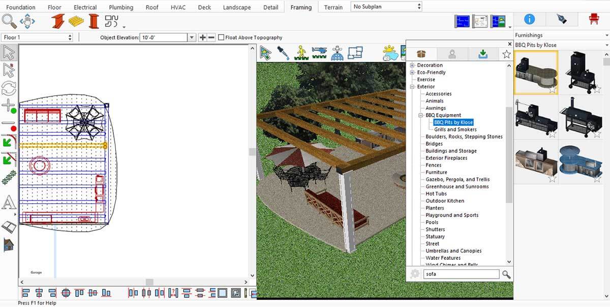
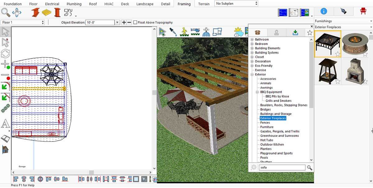
When it comes to selecting the right objects for your living room, you can find many options in the default item library as well as in the downloaded library items. If you want even more choices, you may need to purchase additional power packs for this application.
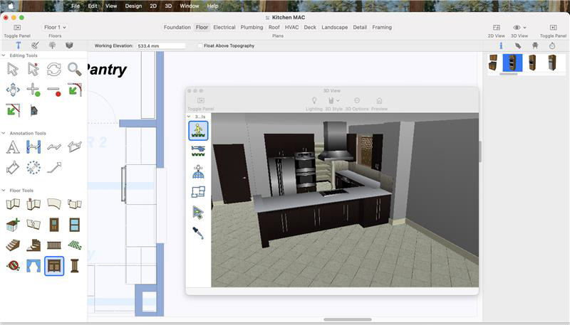
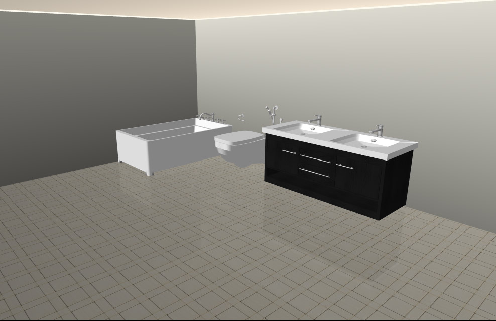
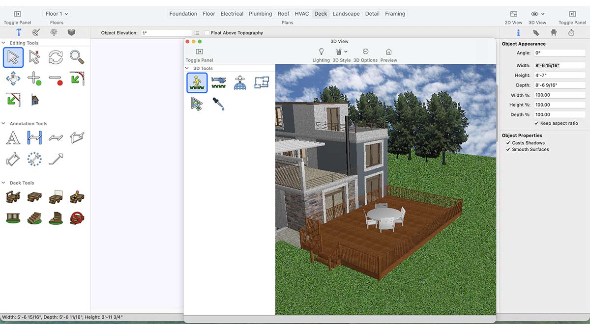
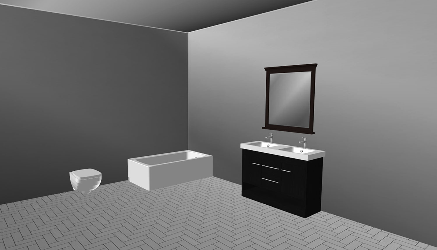
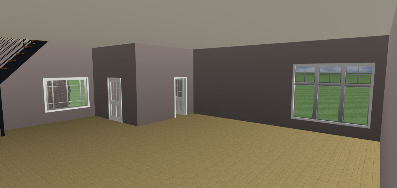
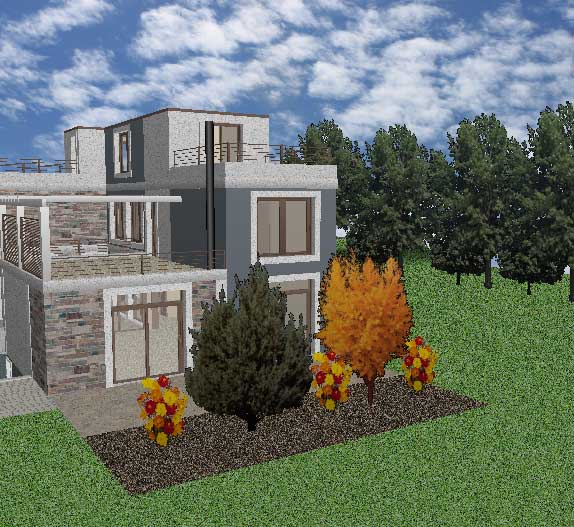
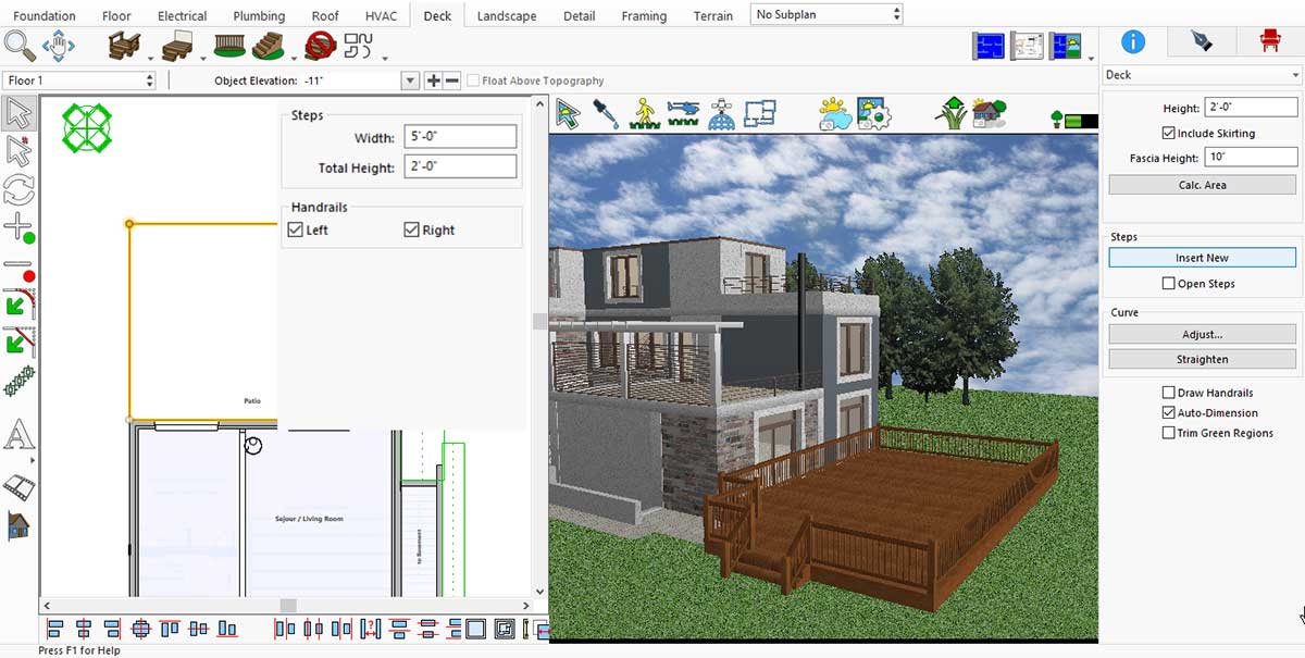
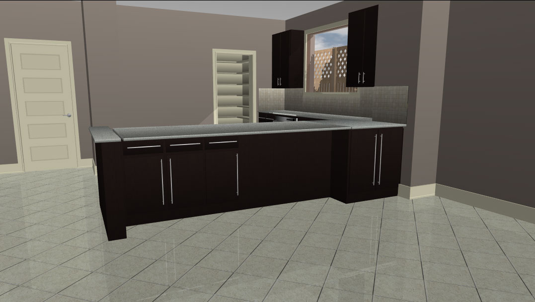
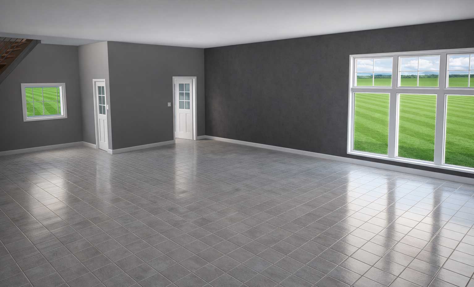
For example, we started with a basic living space that didn’t have any furniture or decor.
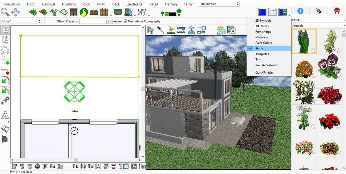
Now it’s time to make our living space more attractive and visually appealing. To do this, we will use the default libraries.
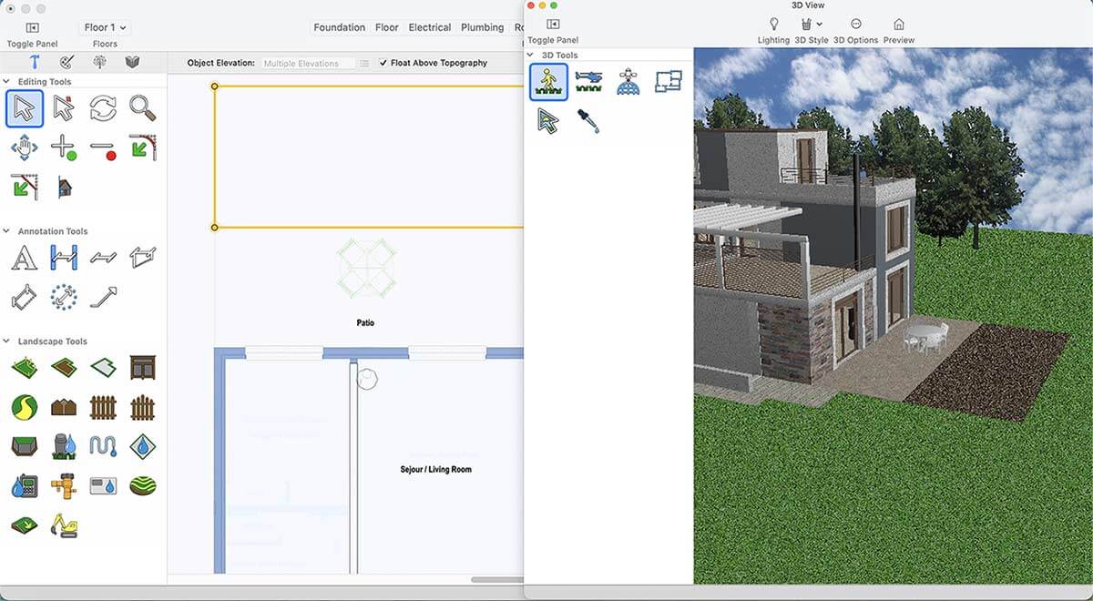
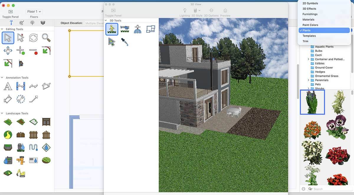
Where we can find default libraries?
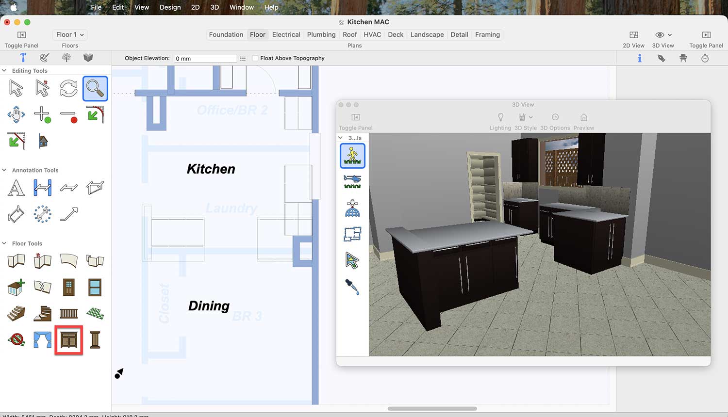
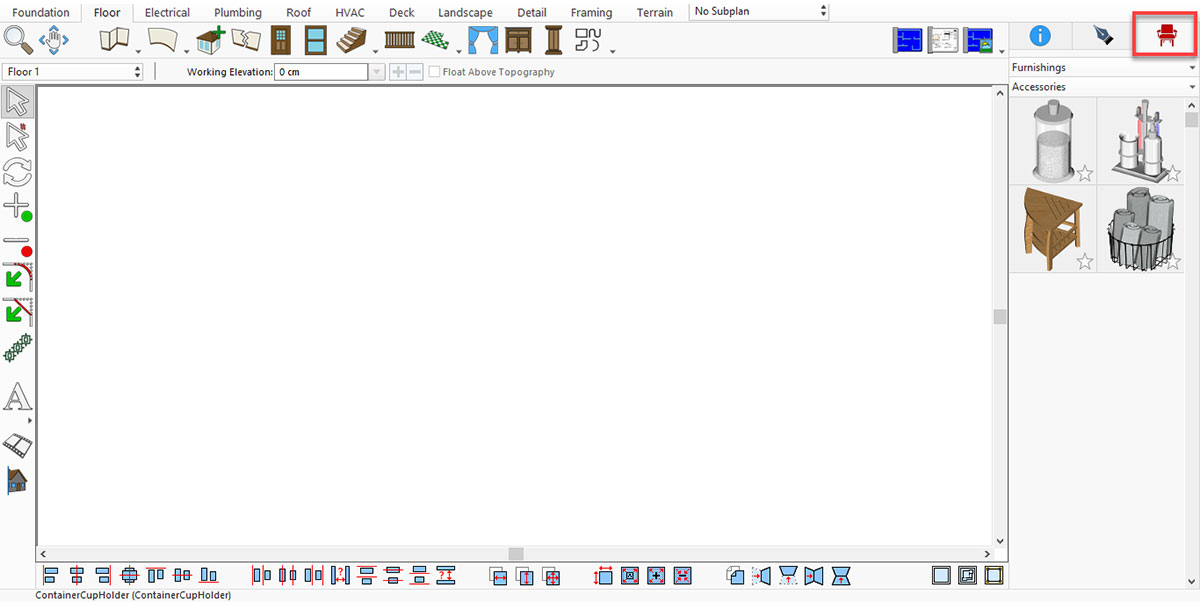
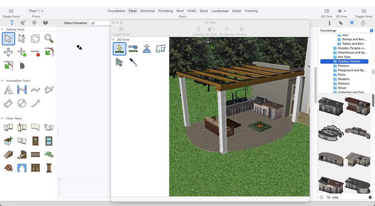
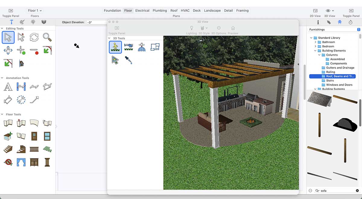
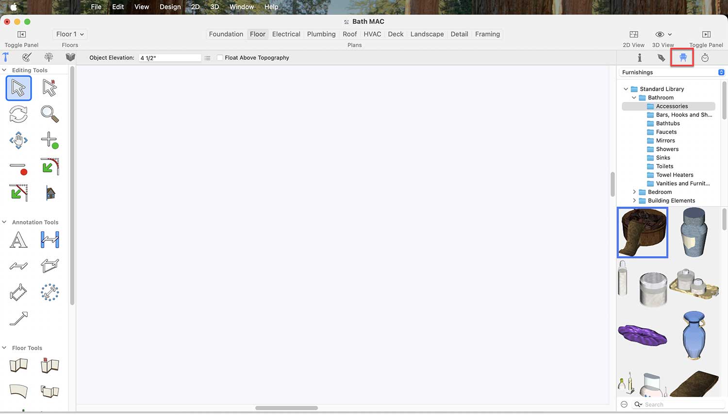
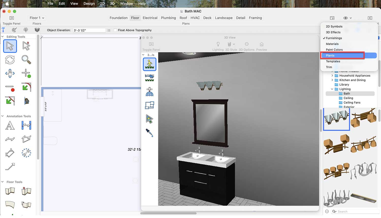
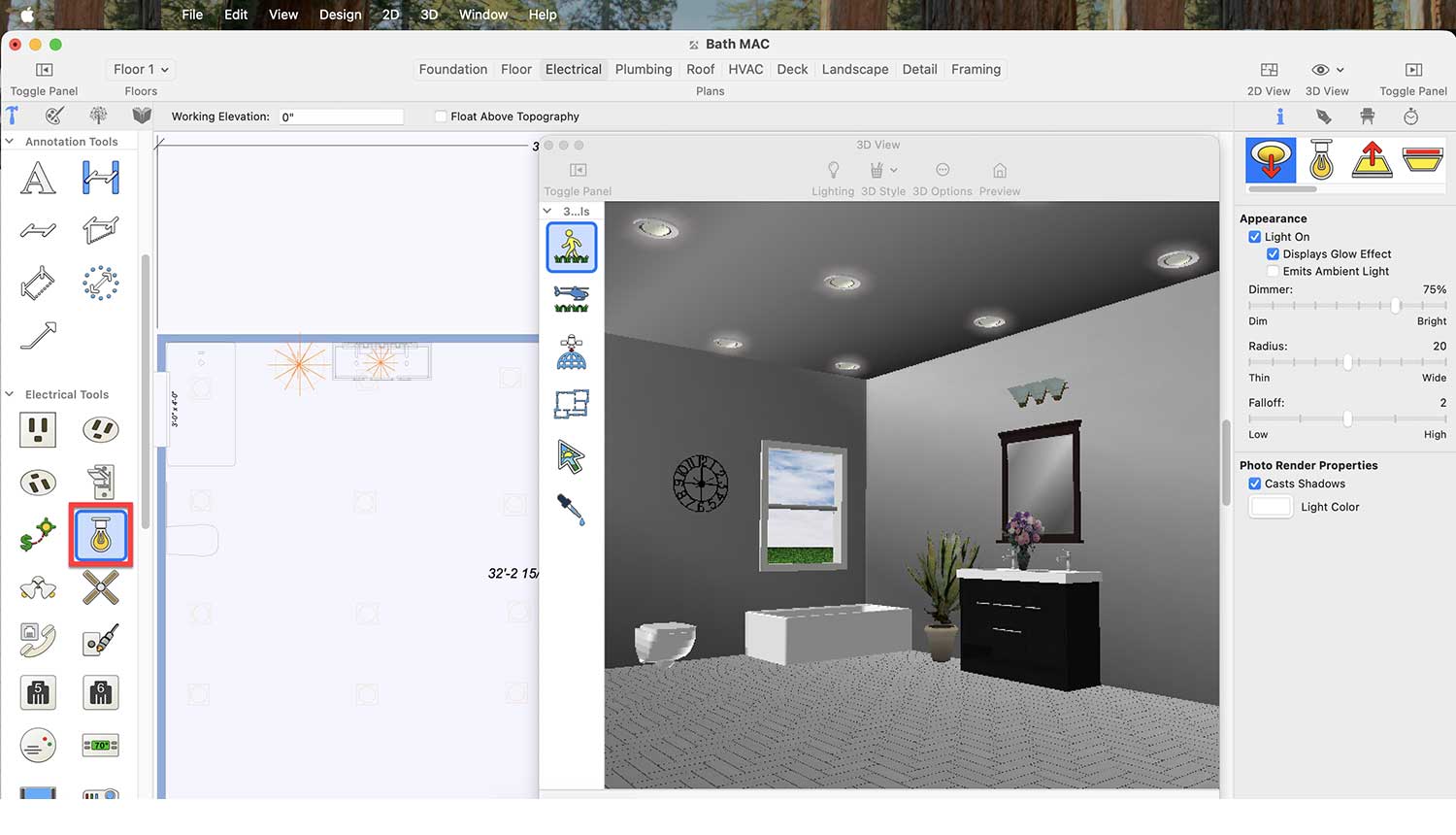
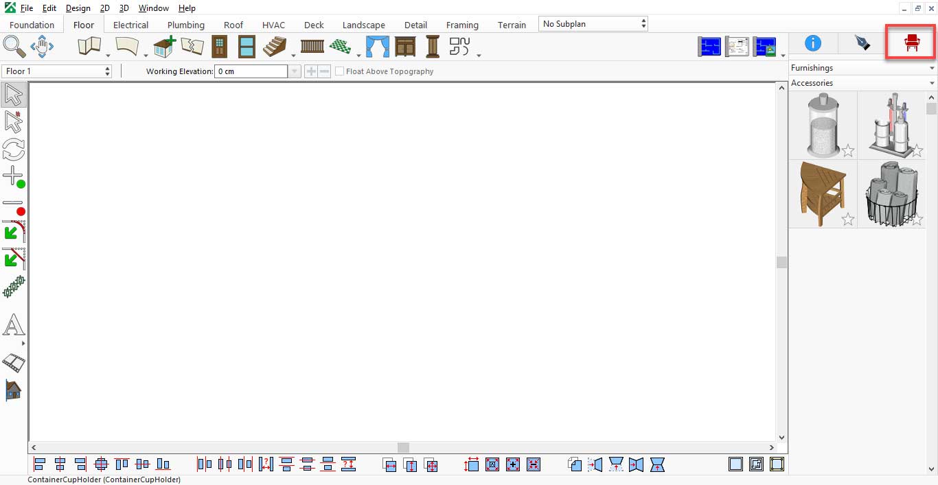
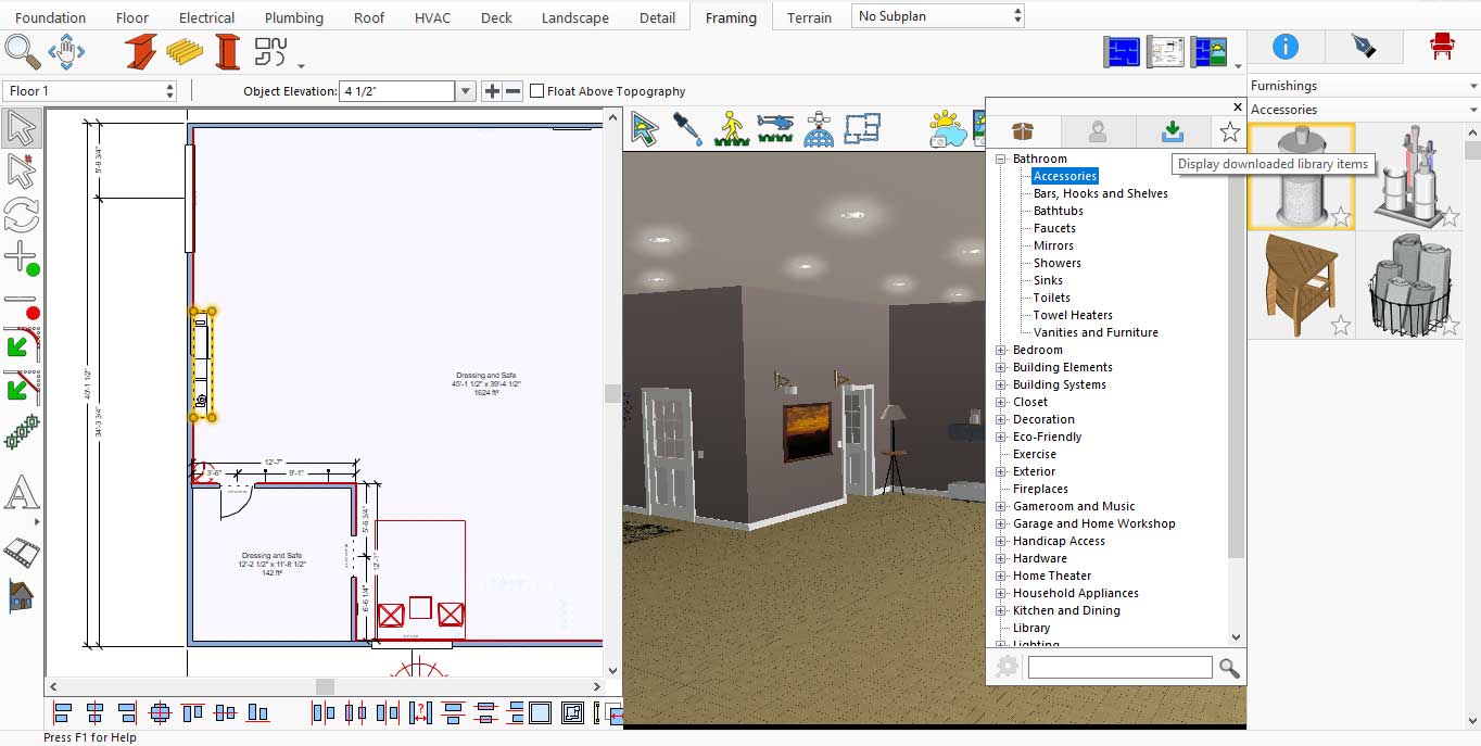
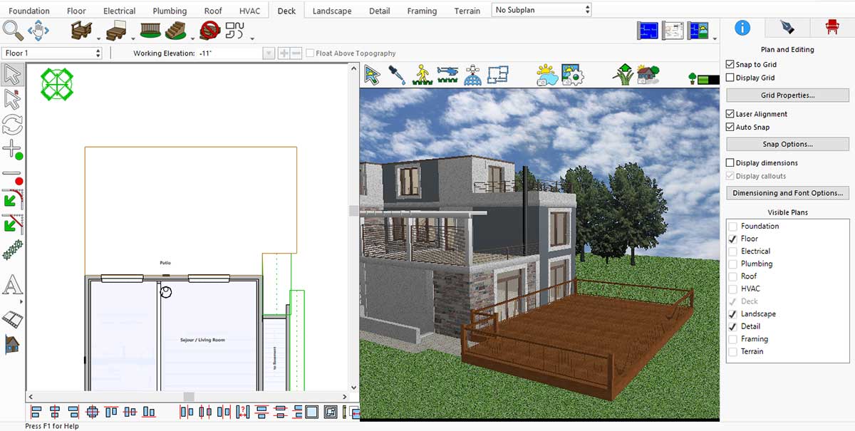
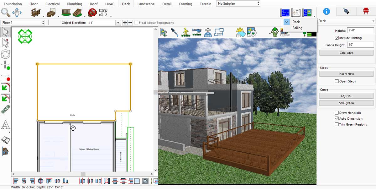
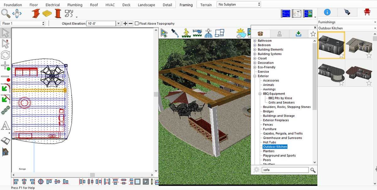
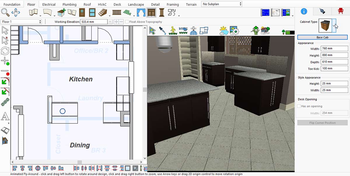
You can find the default library items under Content. To do this, first launch the application and then click on the highlighted icon.
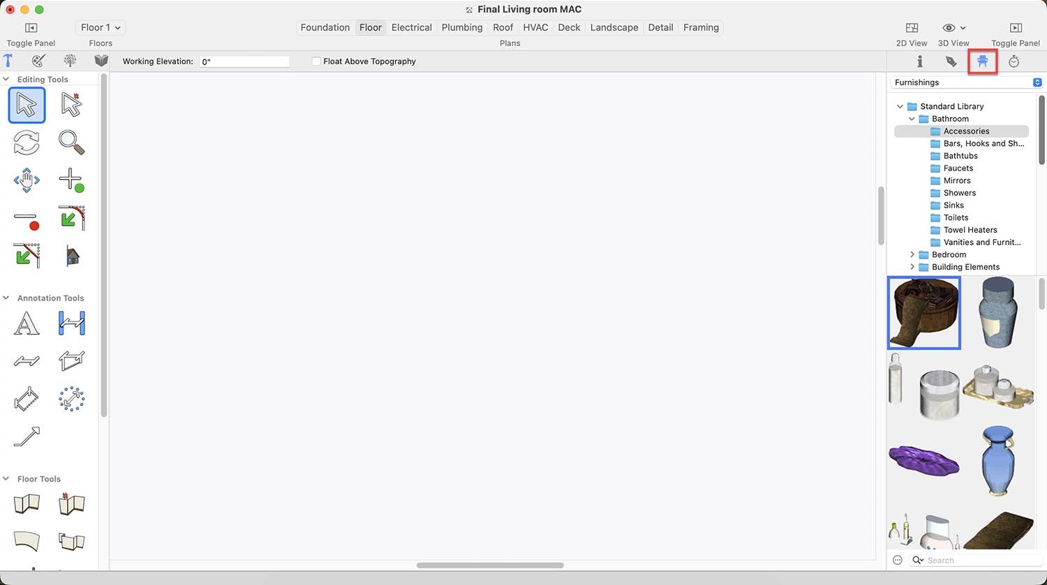
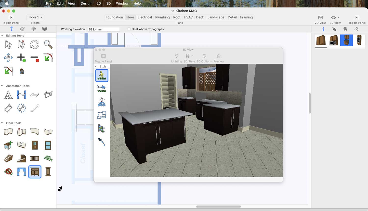
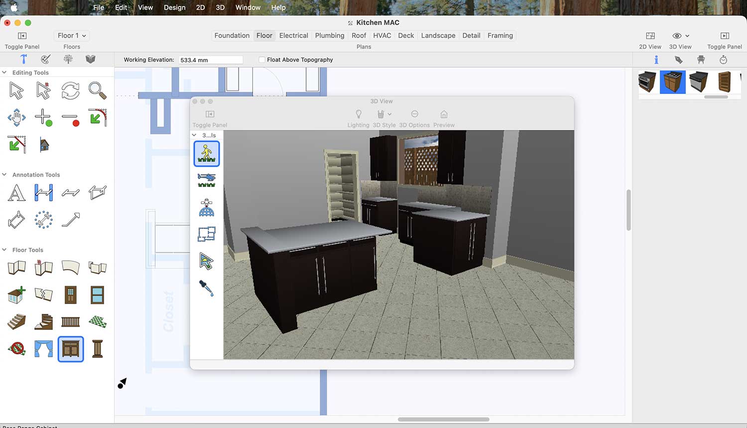
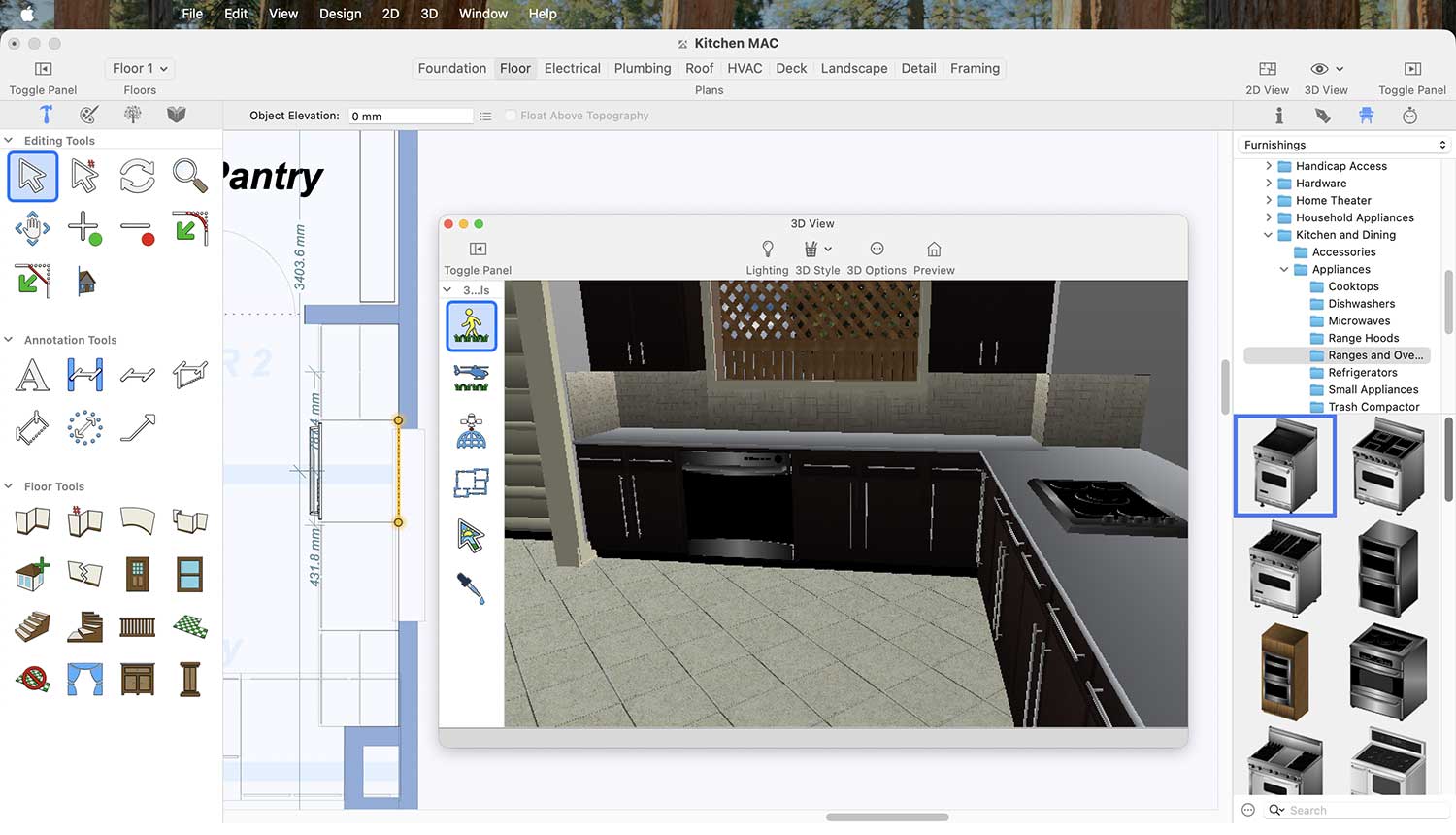
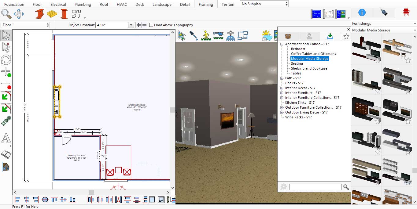
In the Standard Library under Content, you will find some Home Theater Furniture but you may create your own Modular Media Storage for your LED TV. For this you will need to access the Furniture under Office. You may find these under Standard Library > Office > Furniture
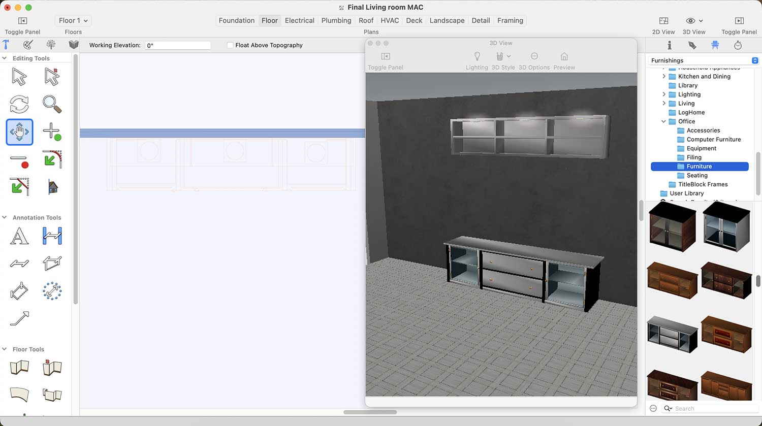
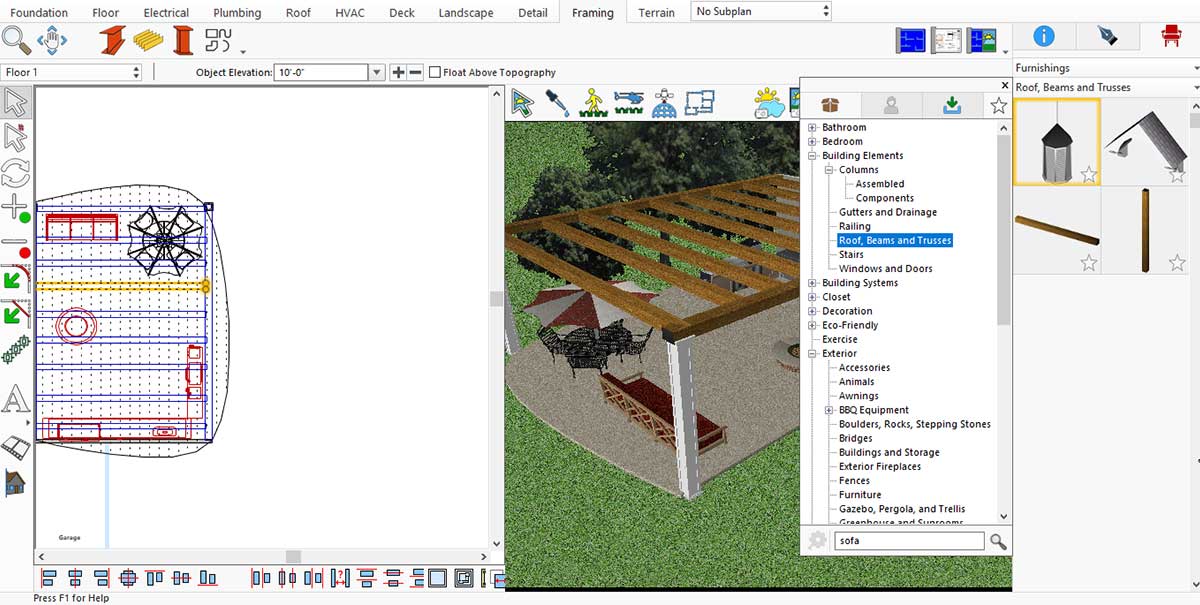
LED Furniture Designs for Living room
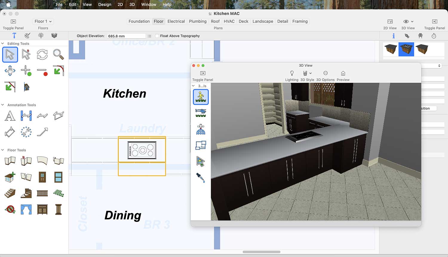
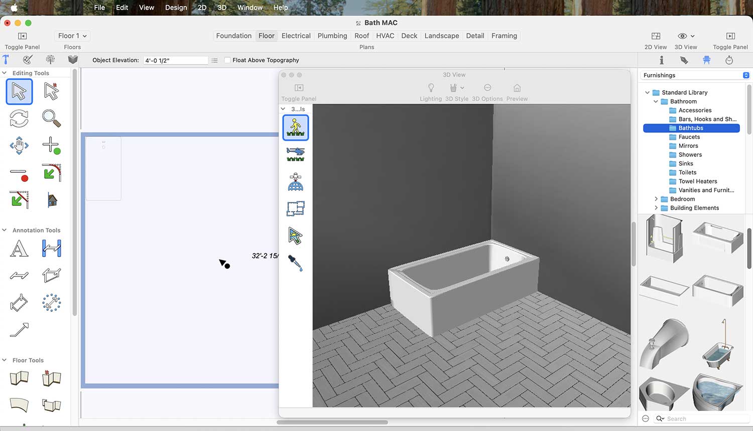
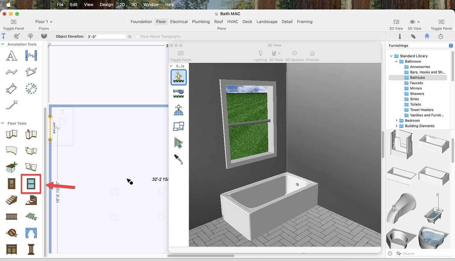
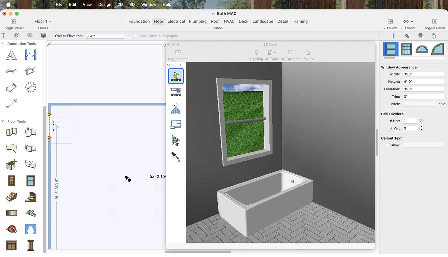
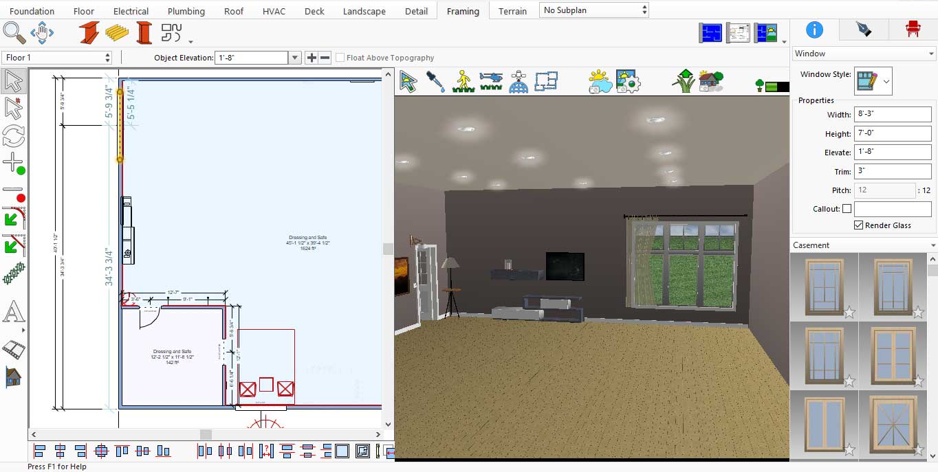
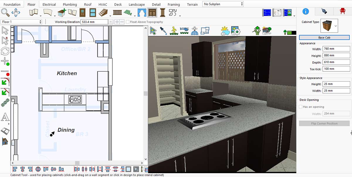
This application offers a wide variety of window designs, and you can choose any one according to your preference for your living room. To place a window in your Living Room you will need to pick the Window icon under Floor tab. After selecting the windows icon when you will simply click on the wall where you want to place the window, it will appear. If you later decide to change the window design, simply click on the added window, and you will see different design options displayed on the right side.
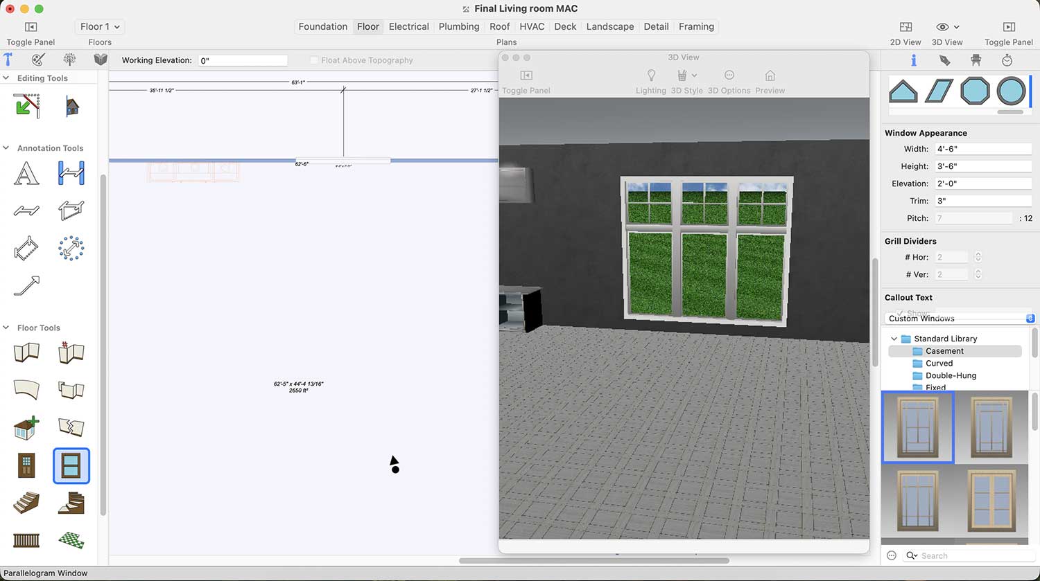
Window Designs for Living room
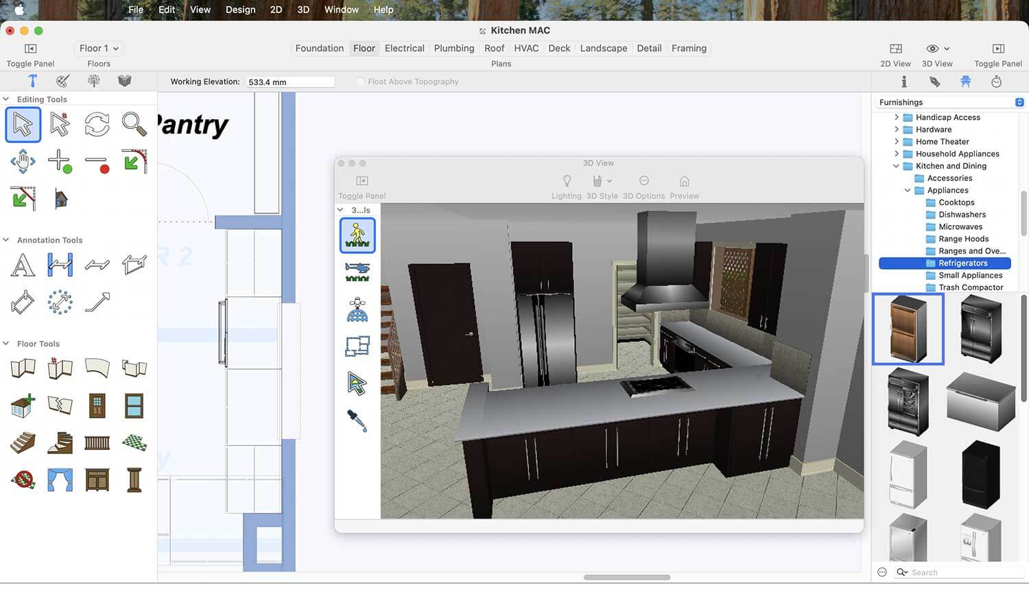
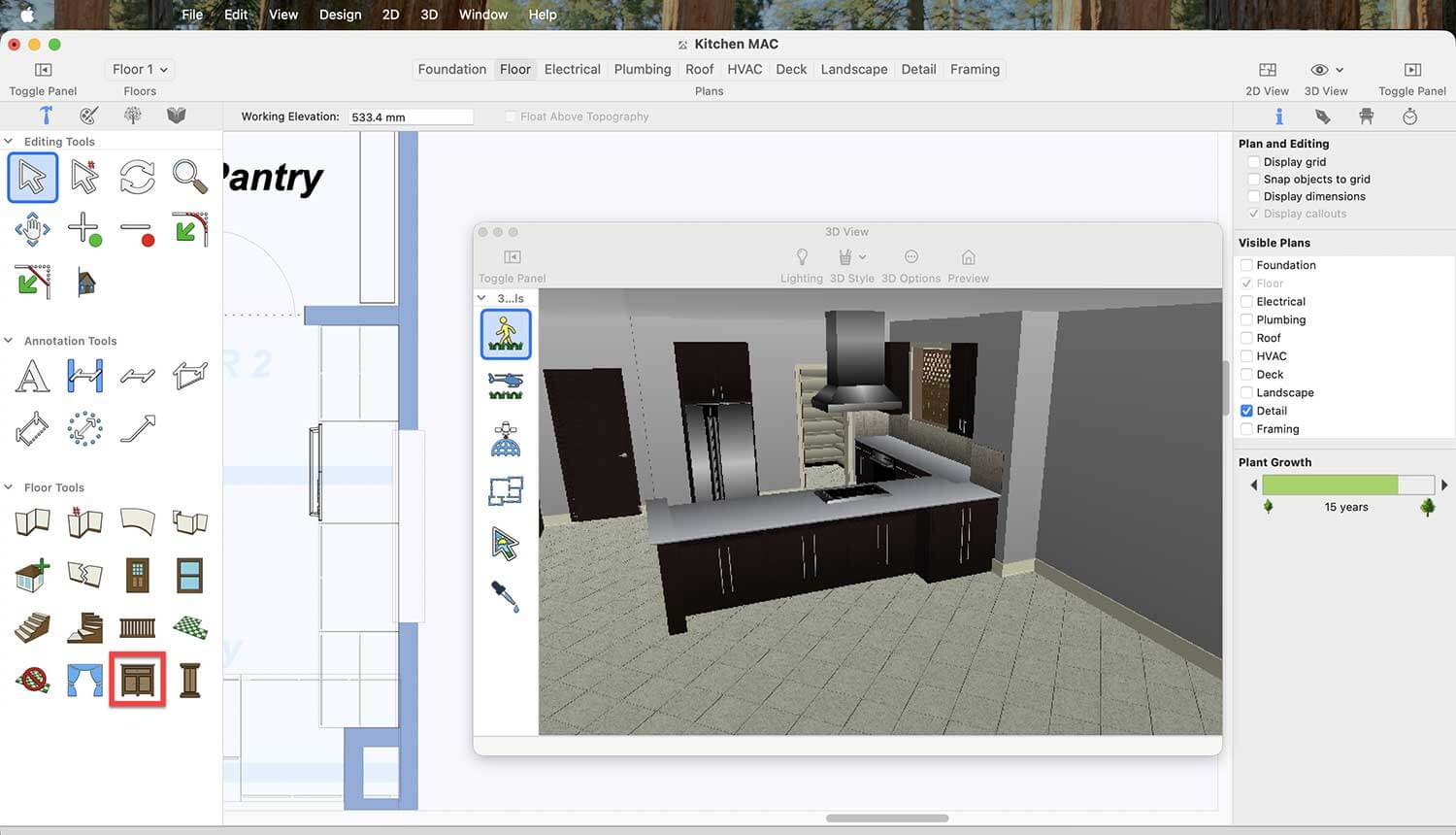
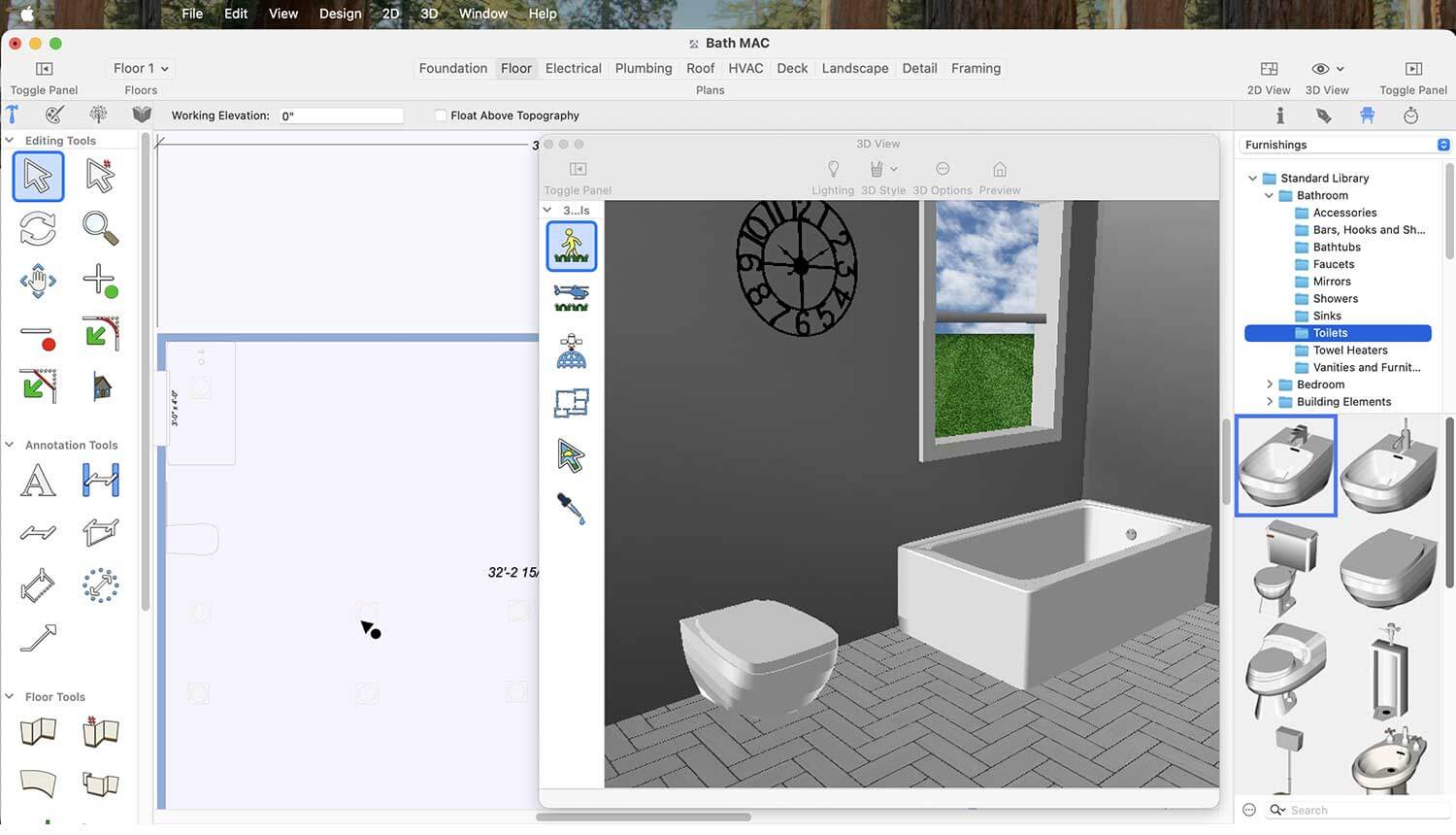
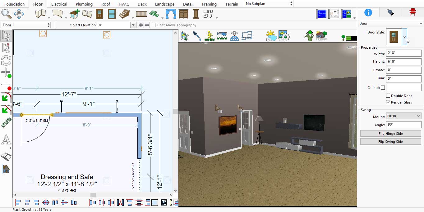
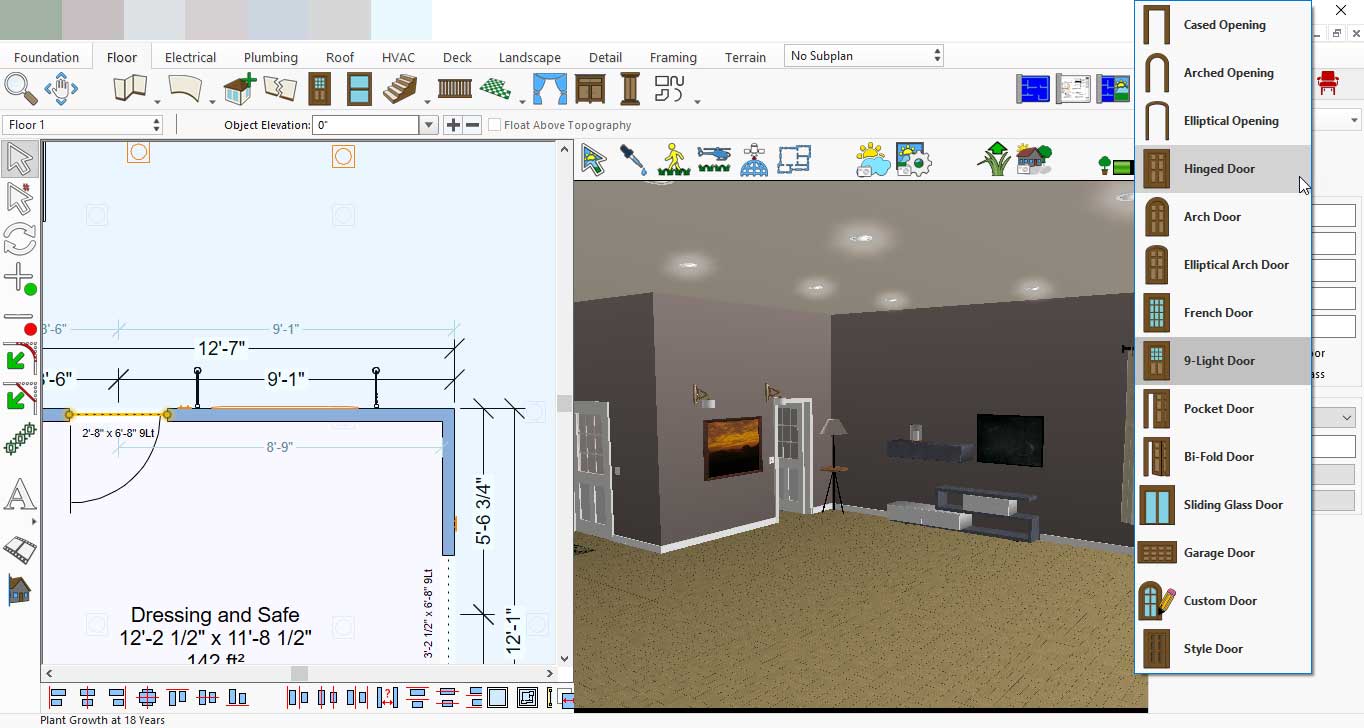
Similarly, this application offers a wide variety of door designs. you can choose any one according to your preference for your living room. To place a door in your Living Room you will need to pick the Door icon under Floor tab.
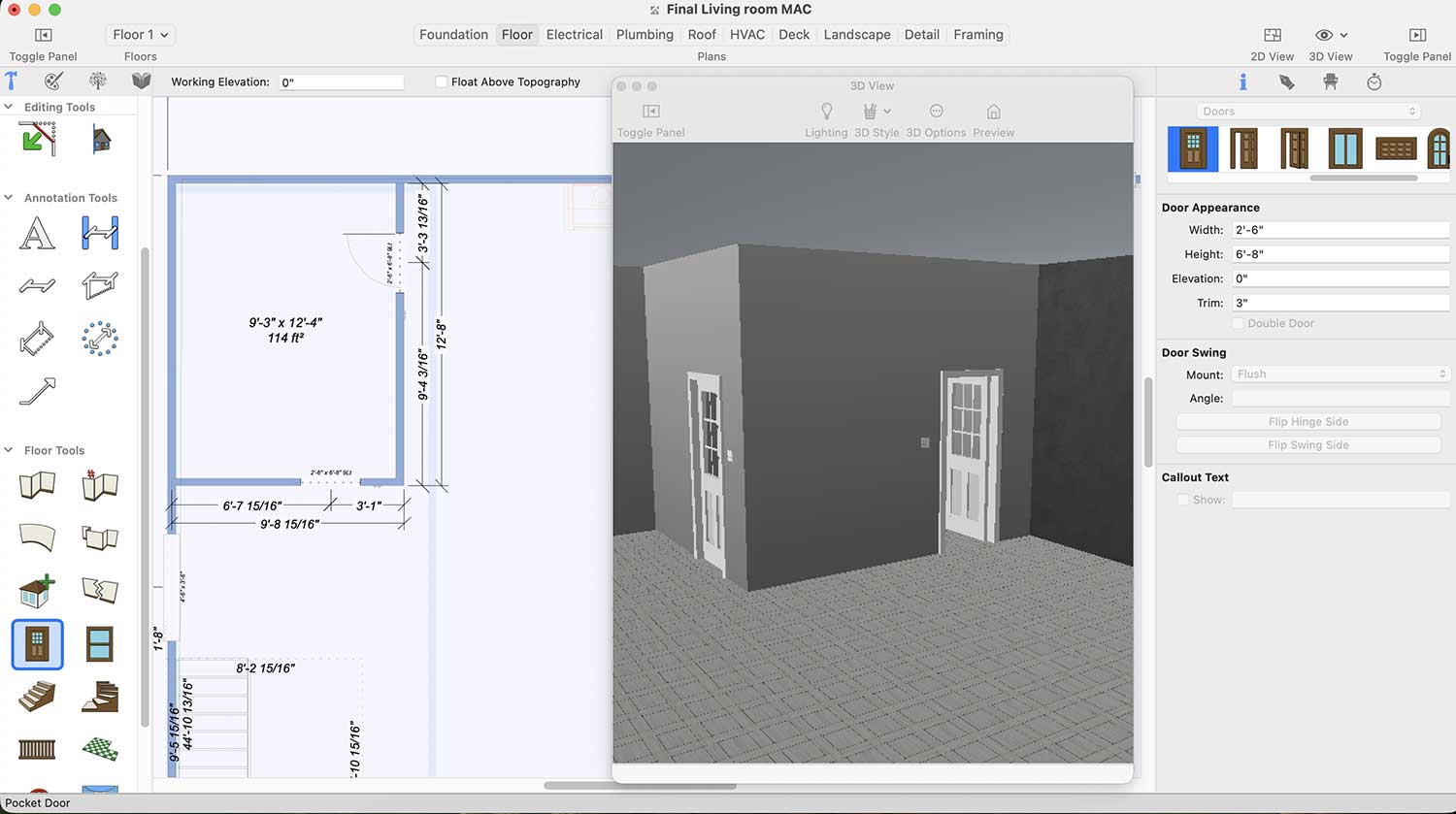
If you decide to change the door design later, simply click on the added door, and the available options will appear on the right side, now when you drag the scroller button left-right, the different door designs will appear.
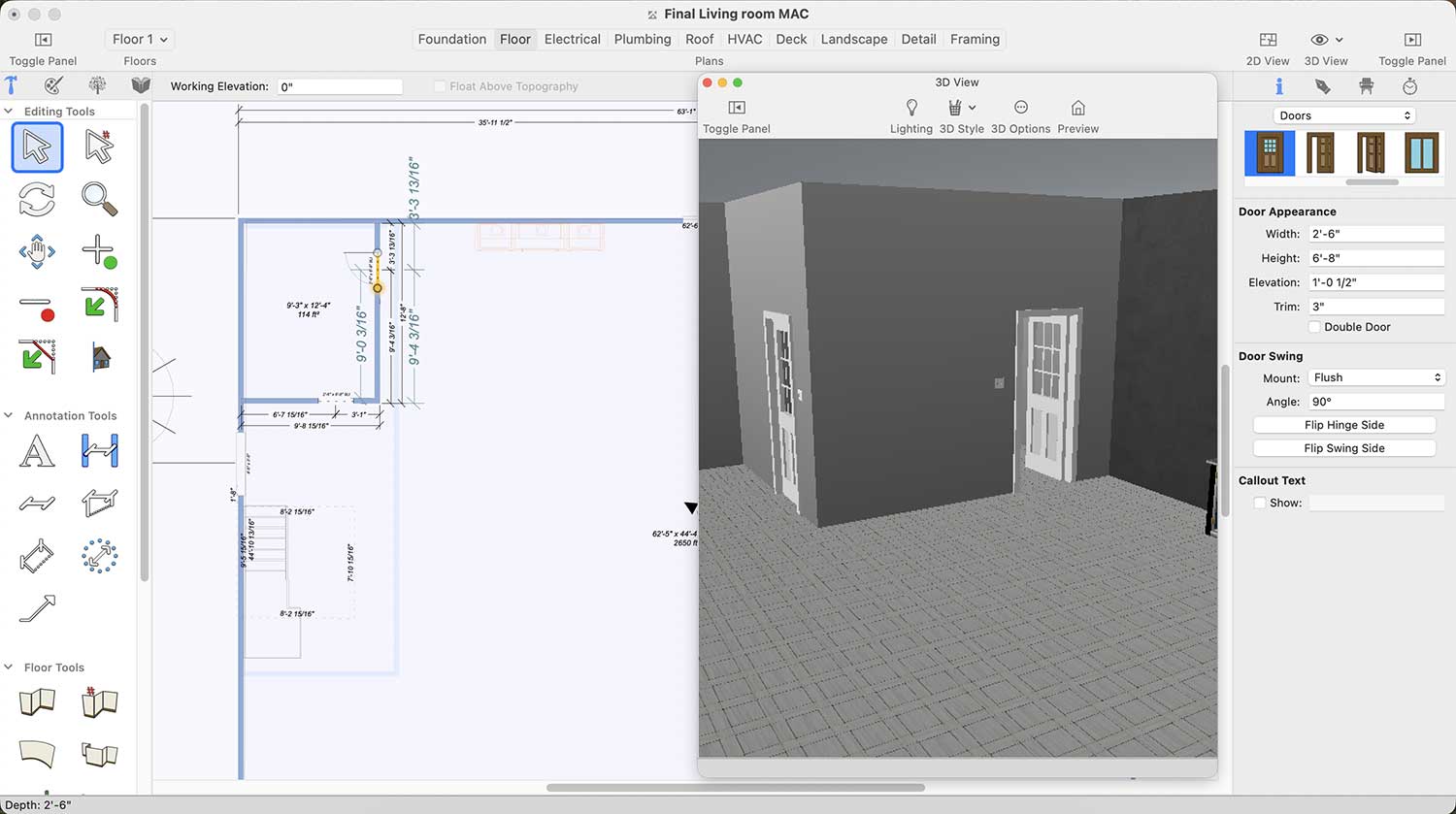
Door Designs for Living room
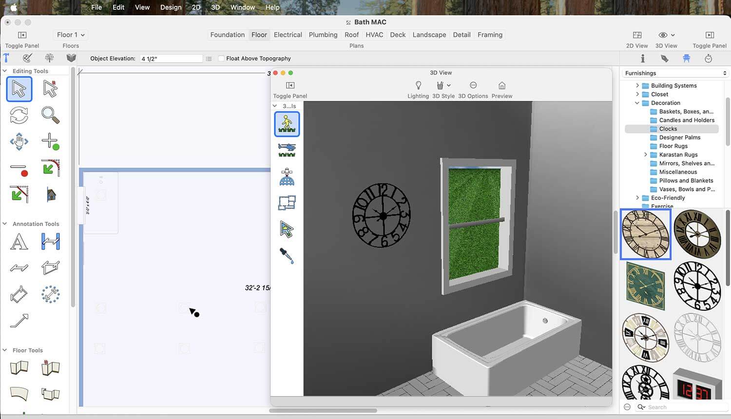
Wall clocks play a vital role in the overall appearance of the living room. Clocks for Living Room can be found under Standard Library > Decoration > Clocks.
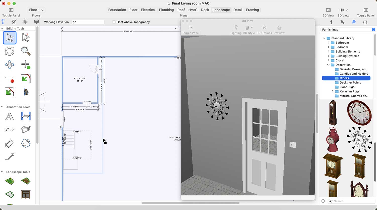
Wall Clocks Collection for Living room
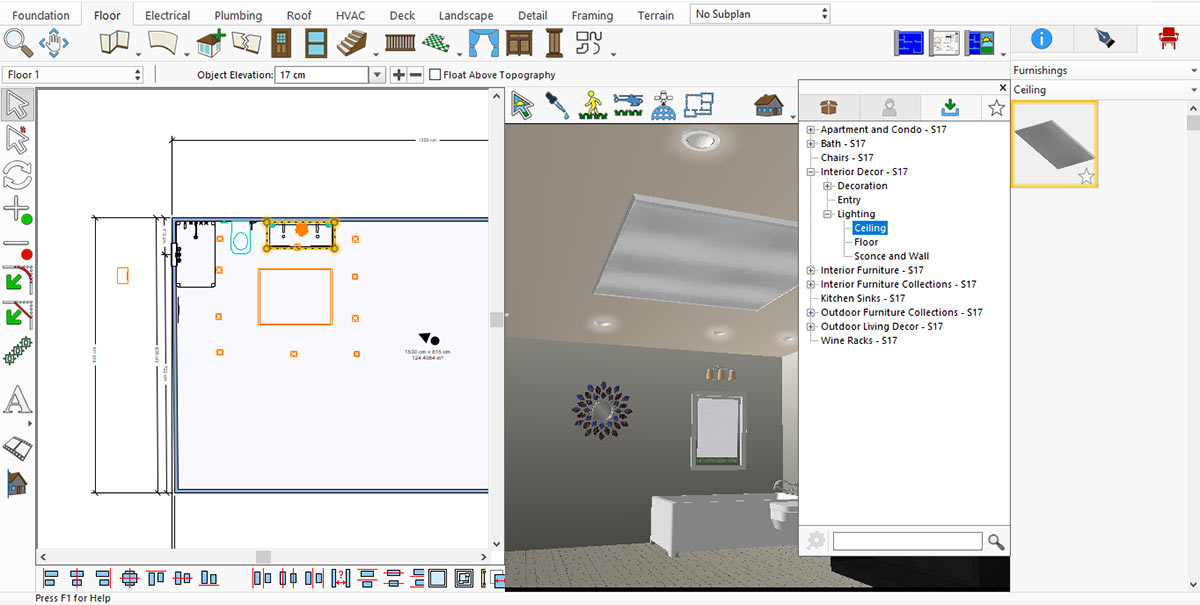
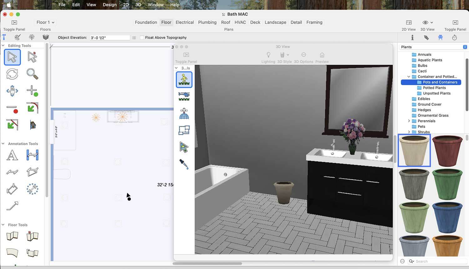
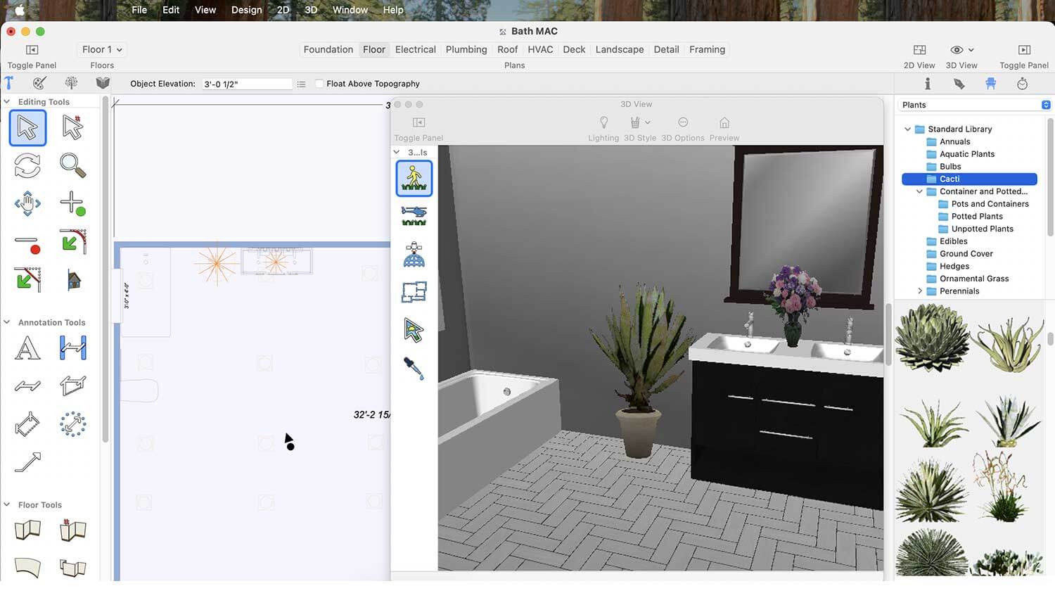
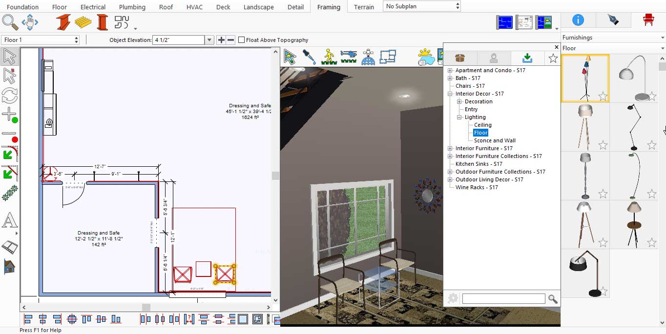
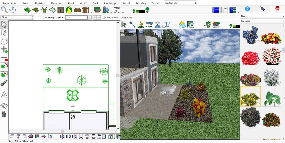
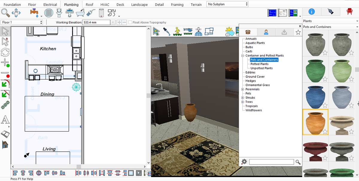
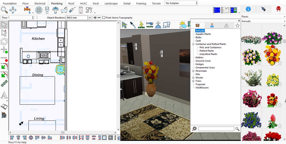
Similarly, floor decoration pieces greatly enhance the overall look of the living room. You may find Floor Decoration Pieces under Standard Library > Lighting > Floor.
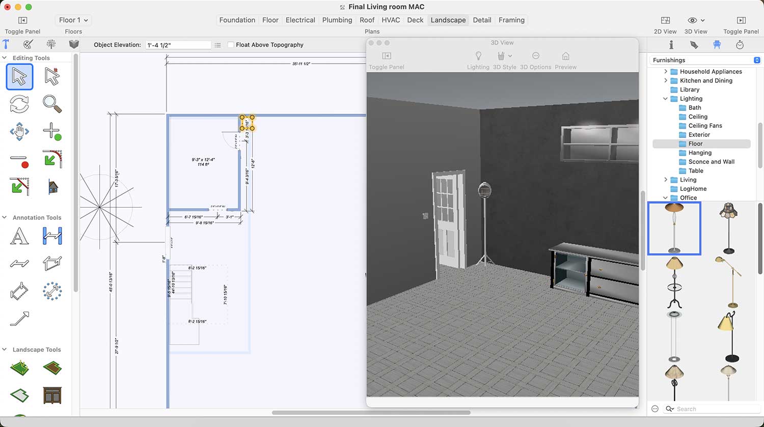
Floor decoration pieces Collection for Living room
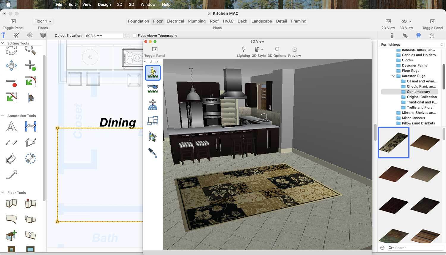
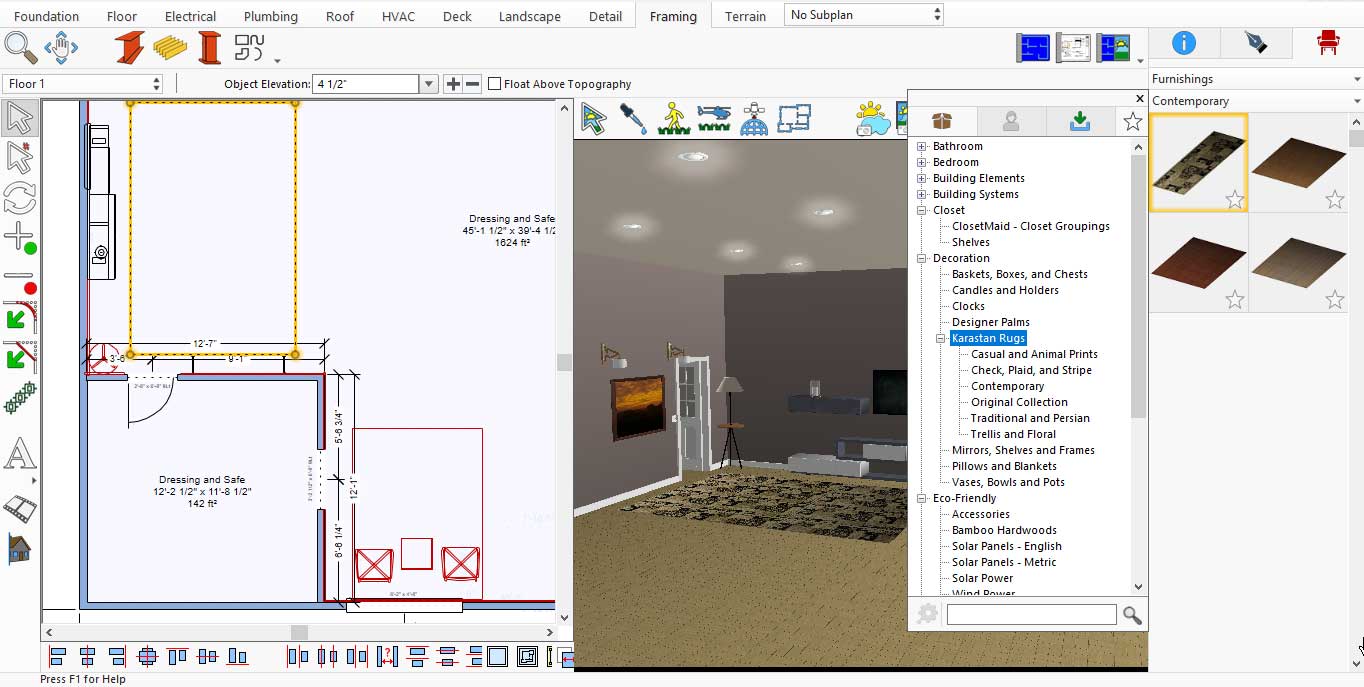
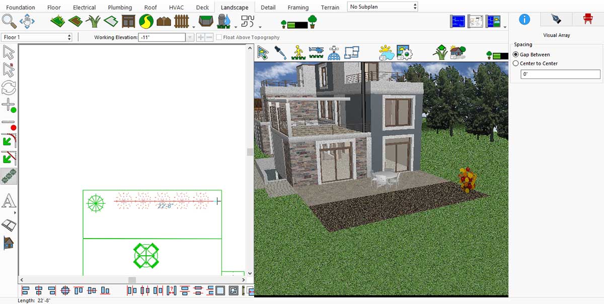
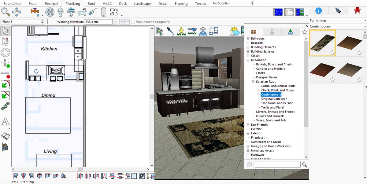
A living room feels incomplete without a carpet. You may find different collection of carpet under Standard Library > Decoration > Karastan Rugs.
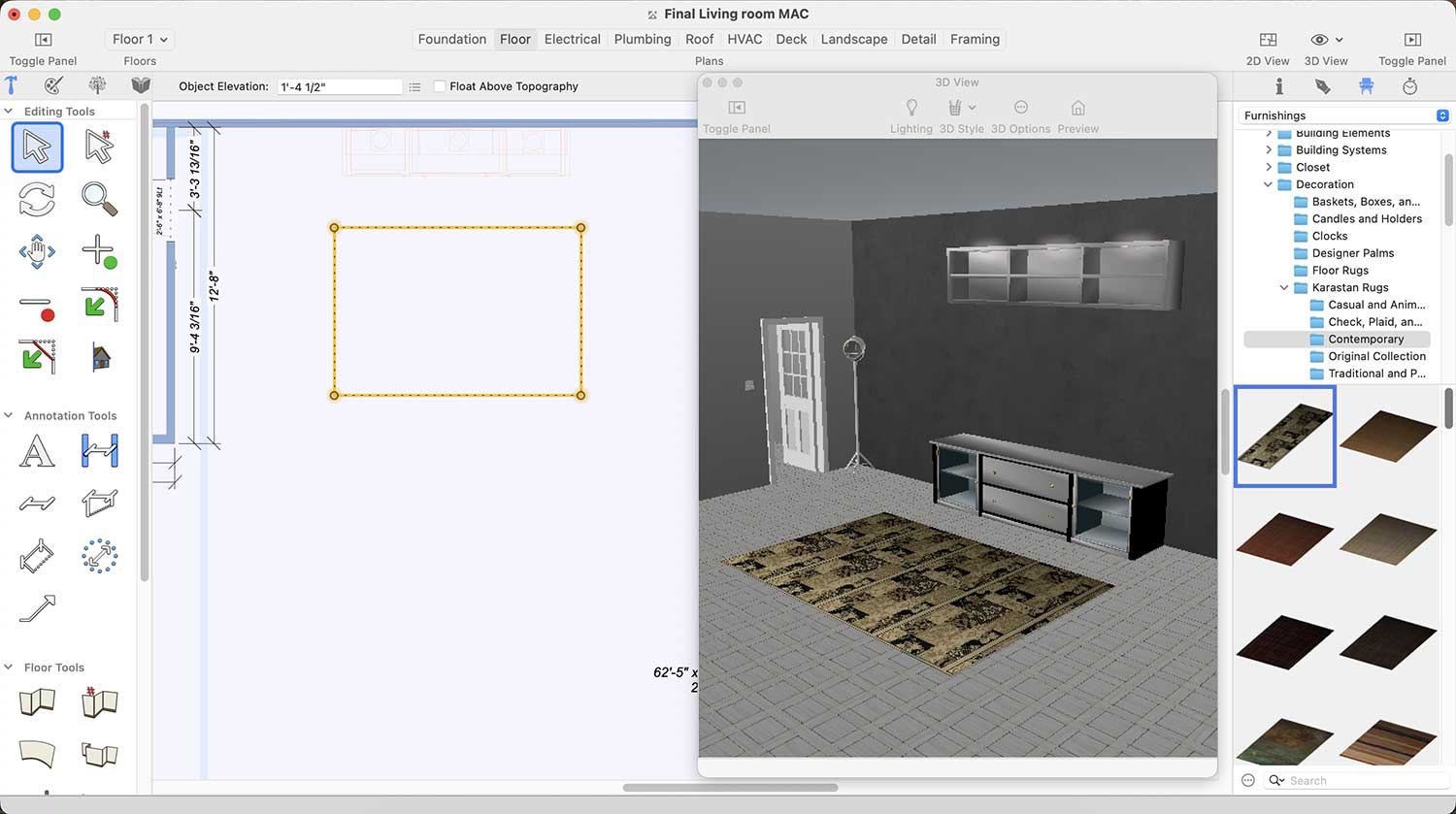
More Designs of Carpets for Living room
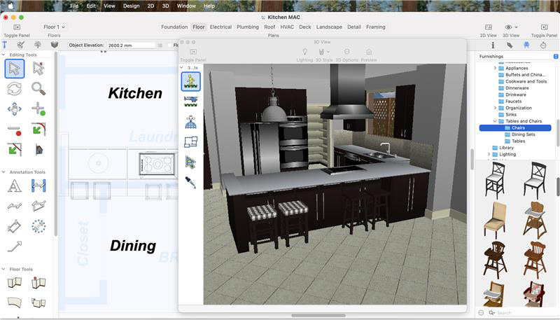
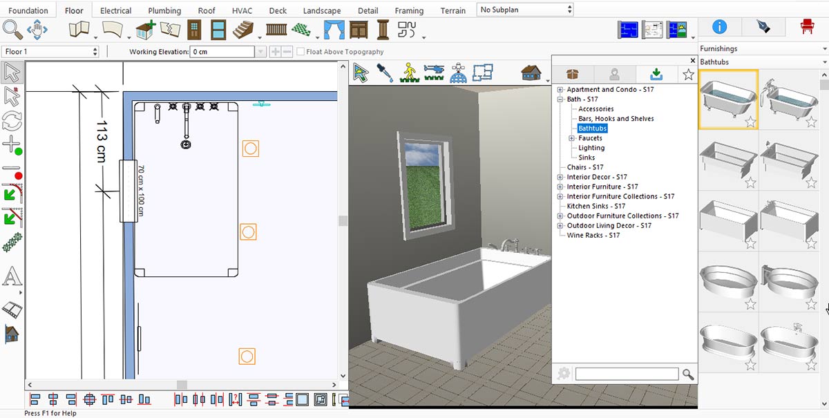
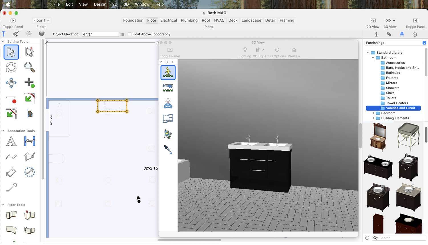
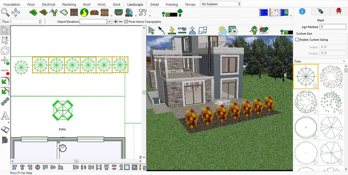
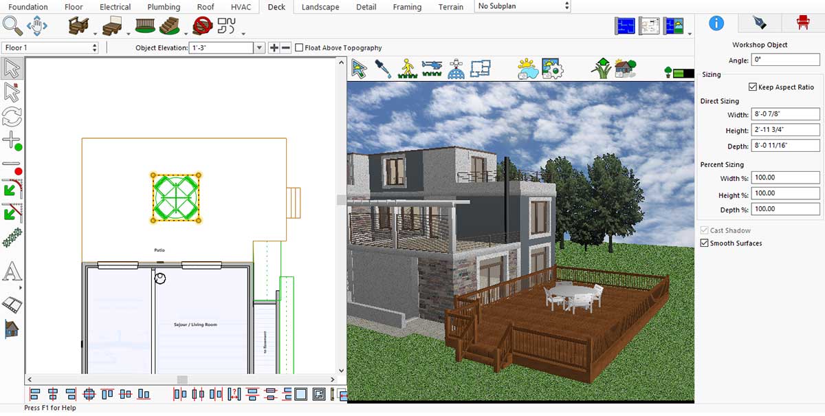
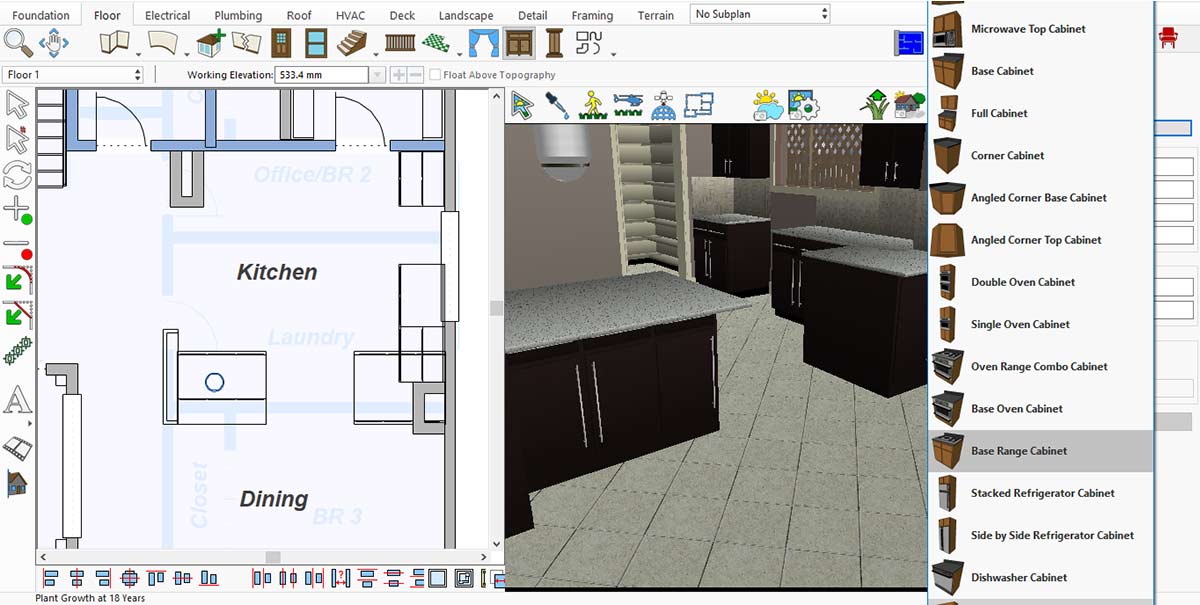
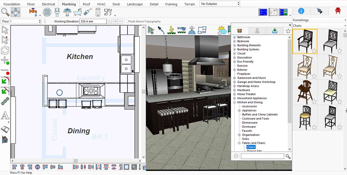
If you want to add furniture, such as a sofa set, to your living room, this application offers a wide variety of designs. You can find them under Standard Library > Living > Sofas and Loveseats.
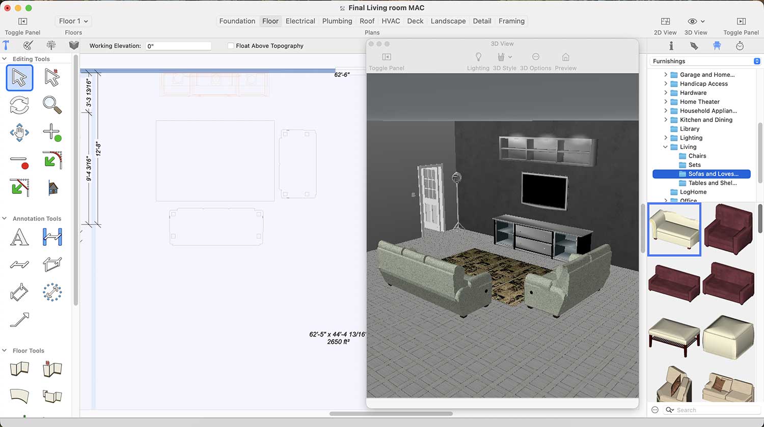
More Designs of Safa set
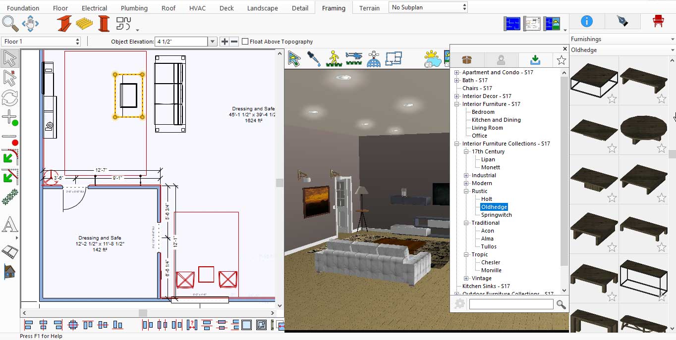
Similarly, if you want to add a table to your living room, there are many tables designs available in this application. You can find them under Standard Library > Living > Tables and Shelving
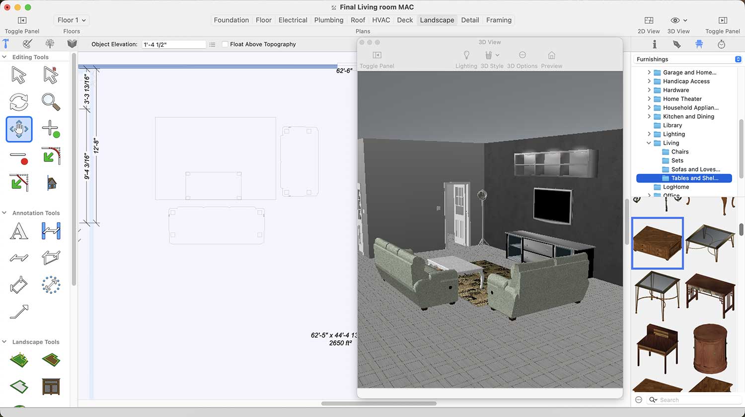
More Designs of Tables for Living room
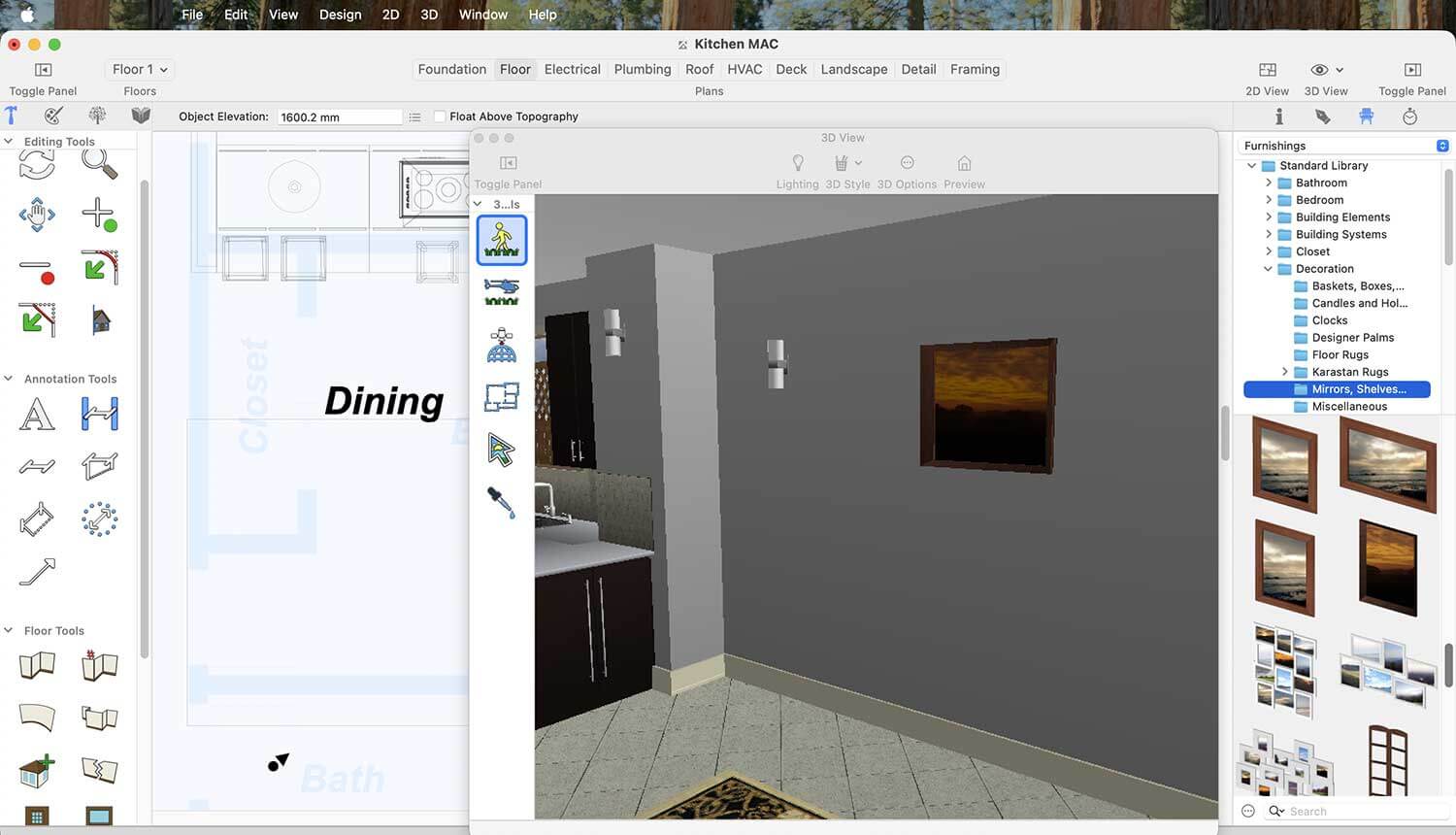
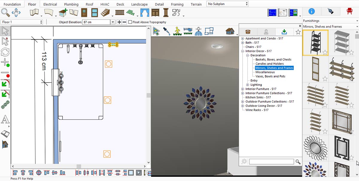
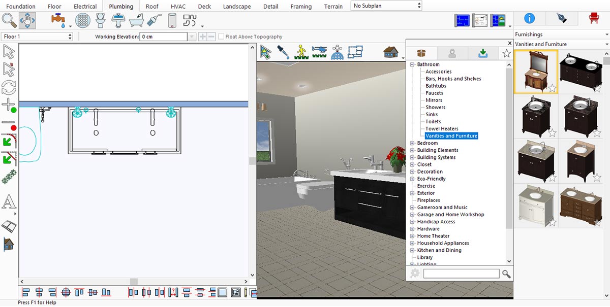
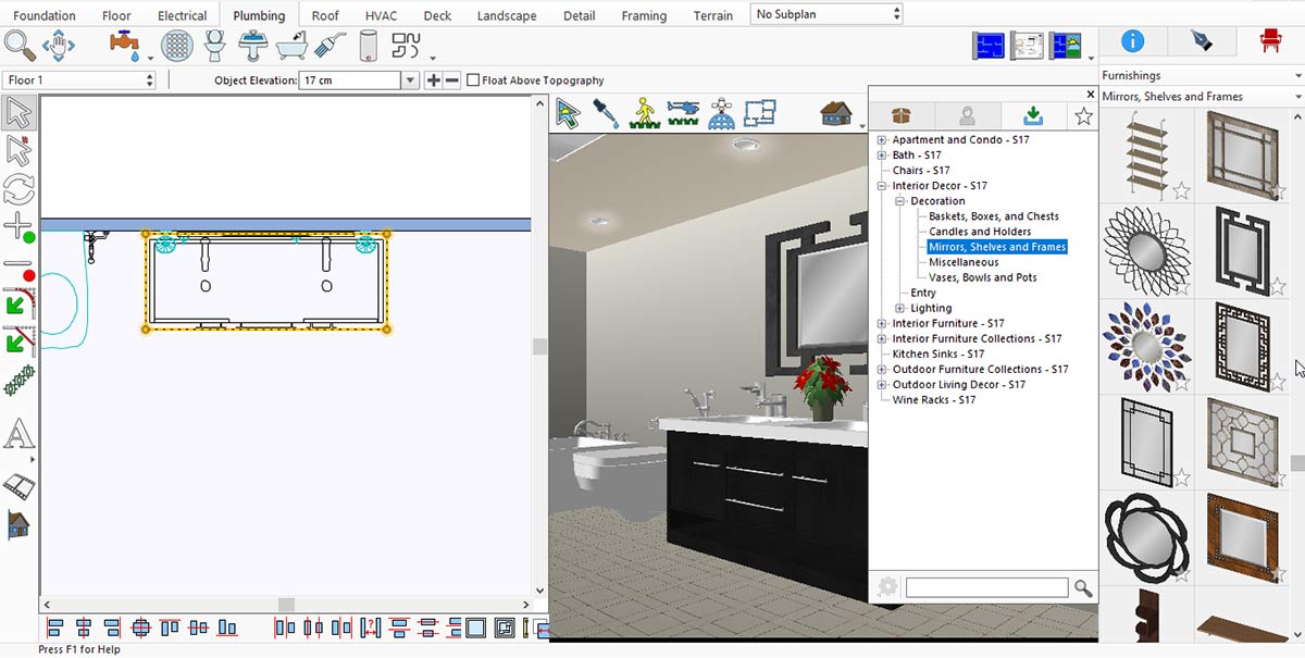
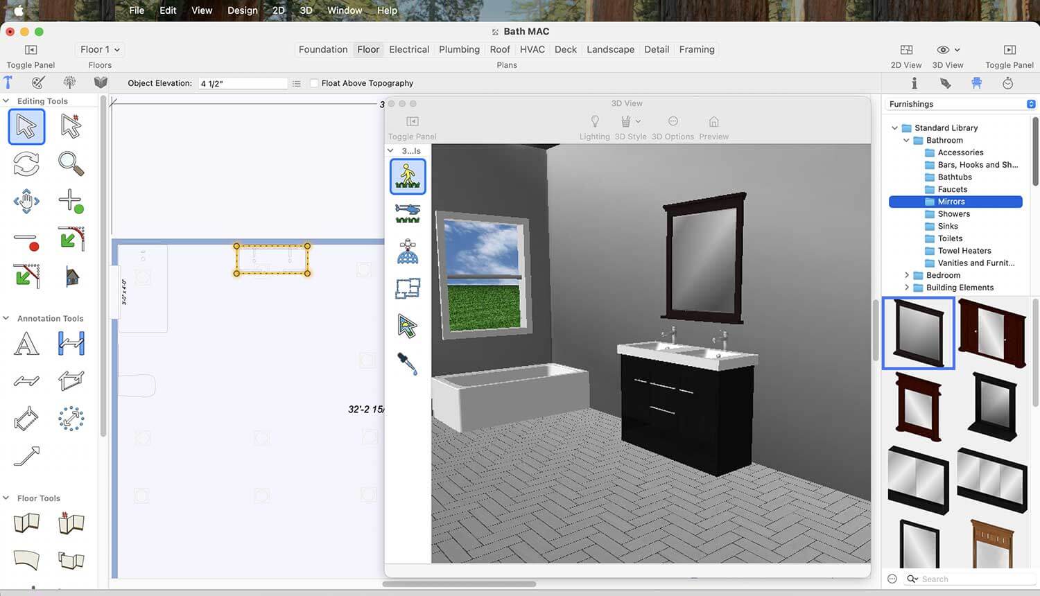
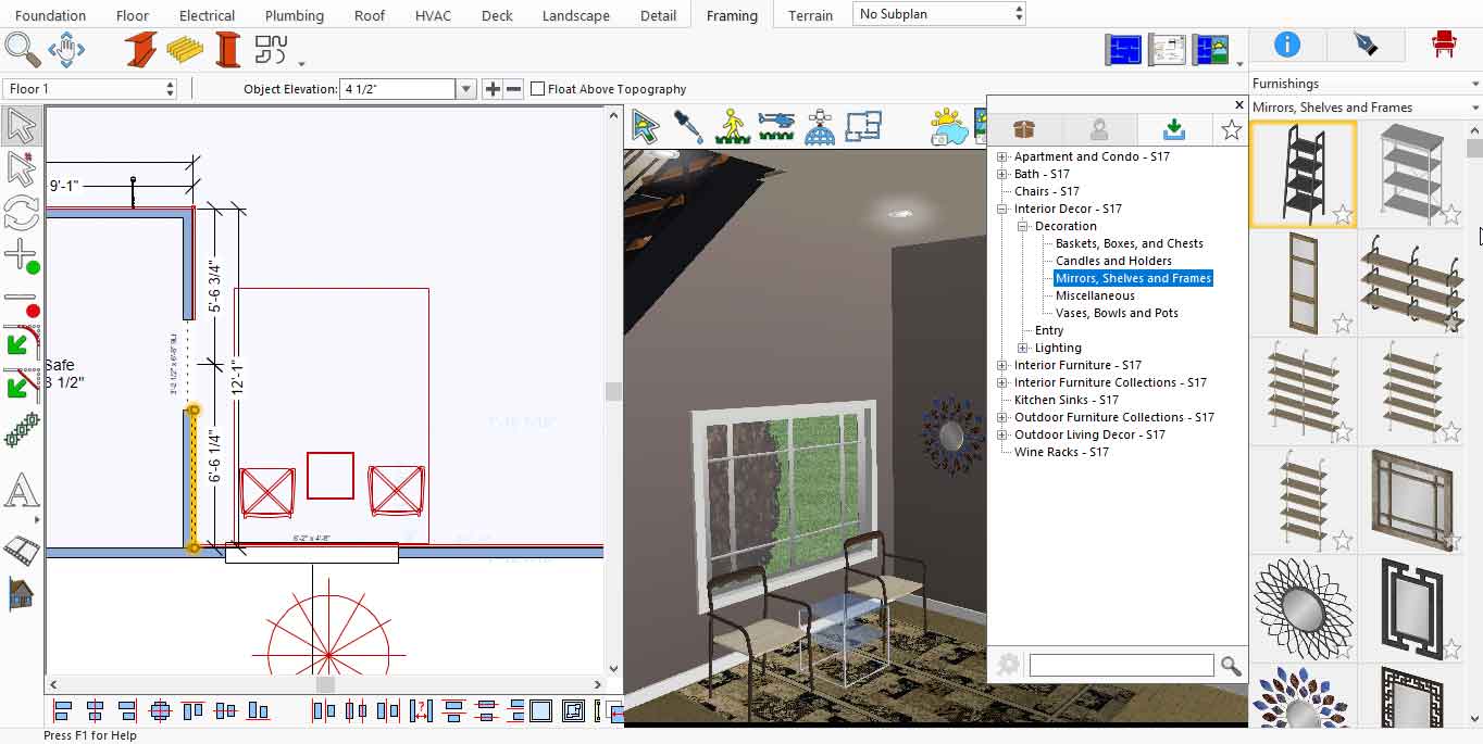
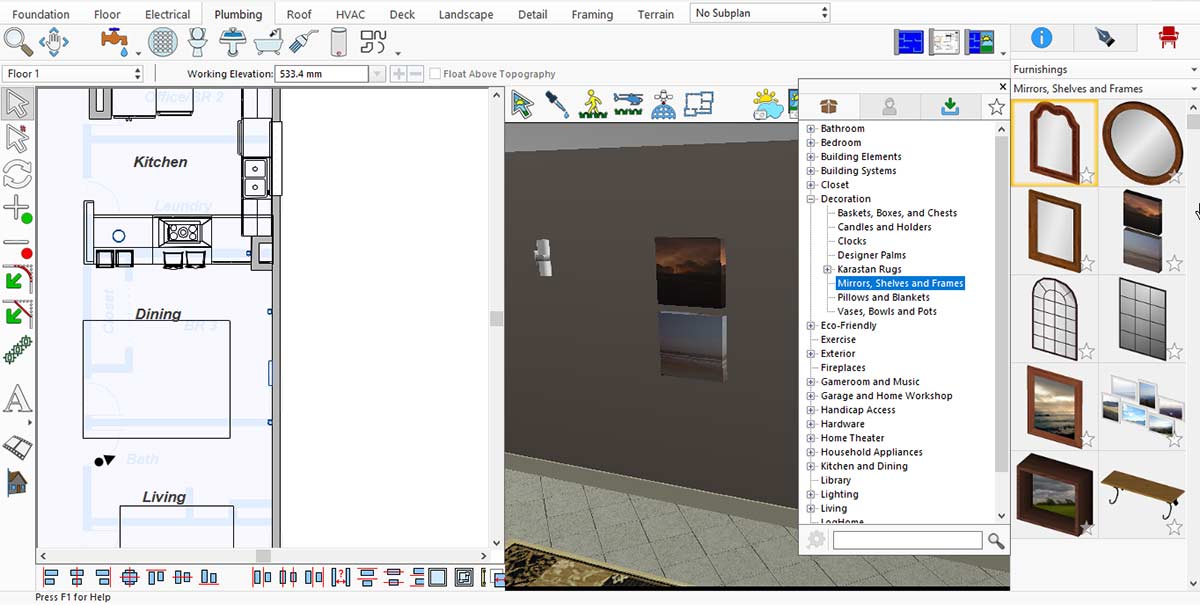
Framed images on the walls contribute to a modern Living Room. To place them, go to Standard Library > Decoration > Mirrors, Shelves, and Frames.
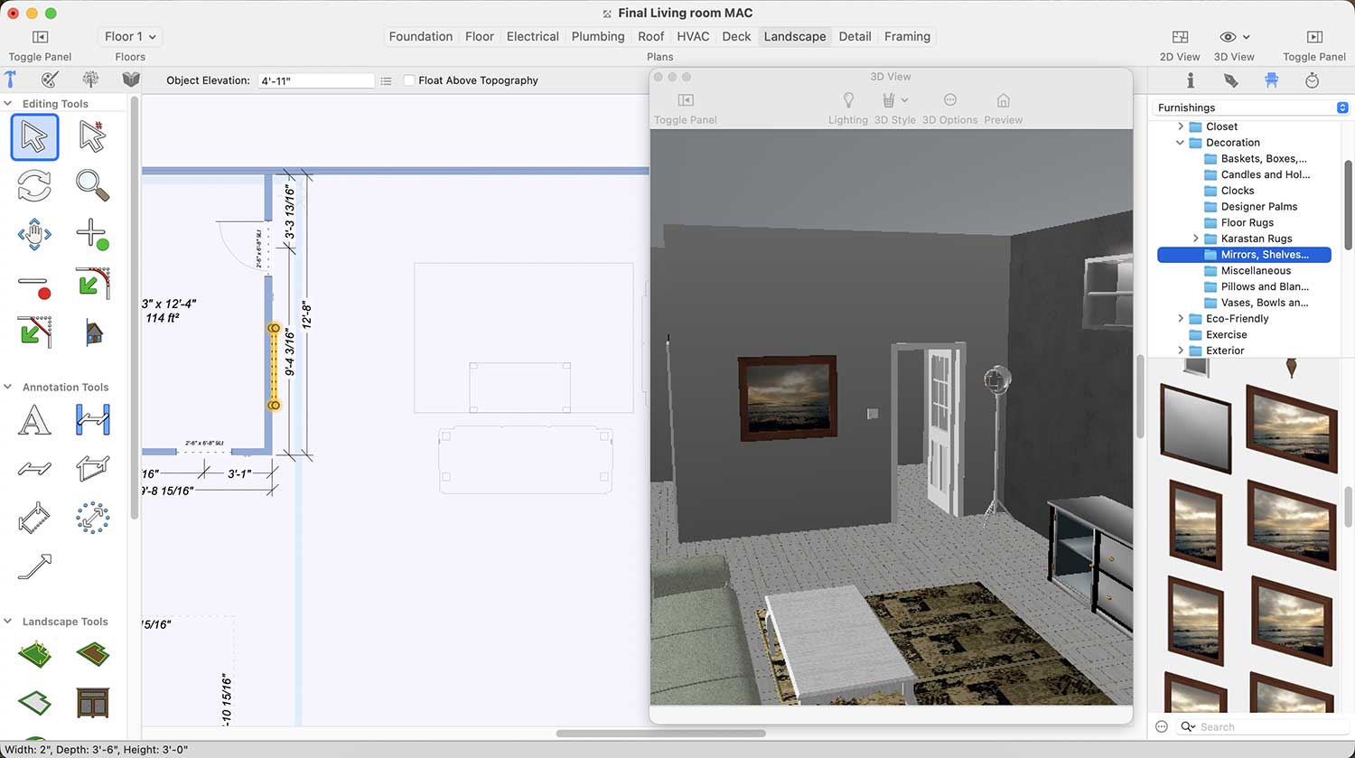
Framed Image Collection for Living room
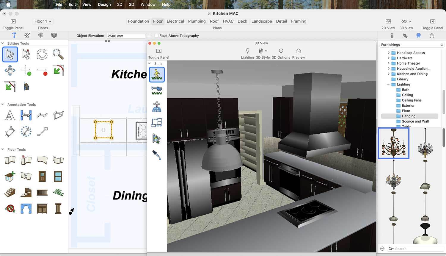
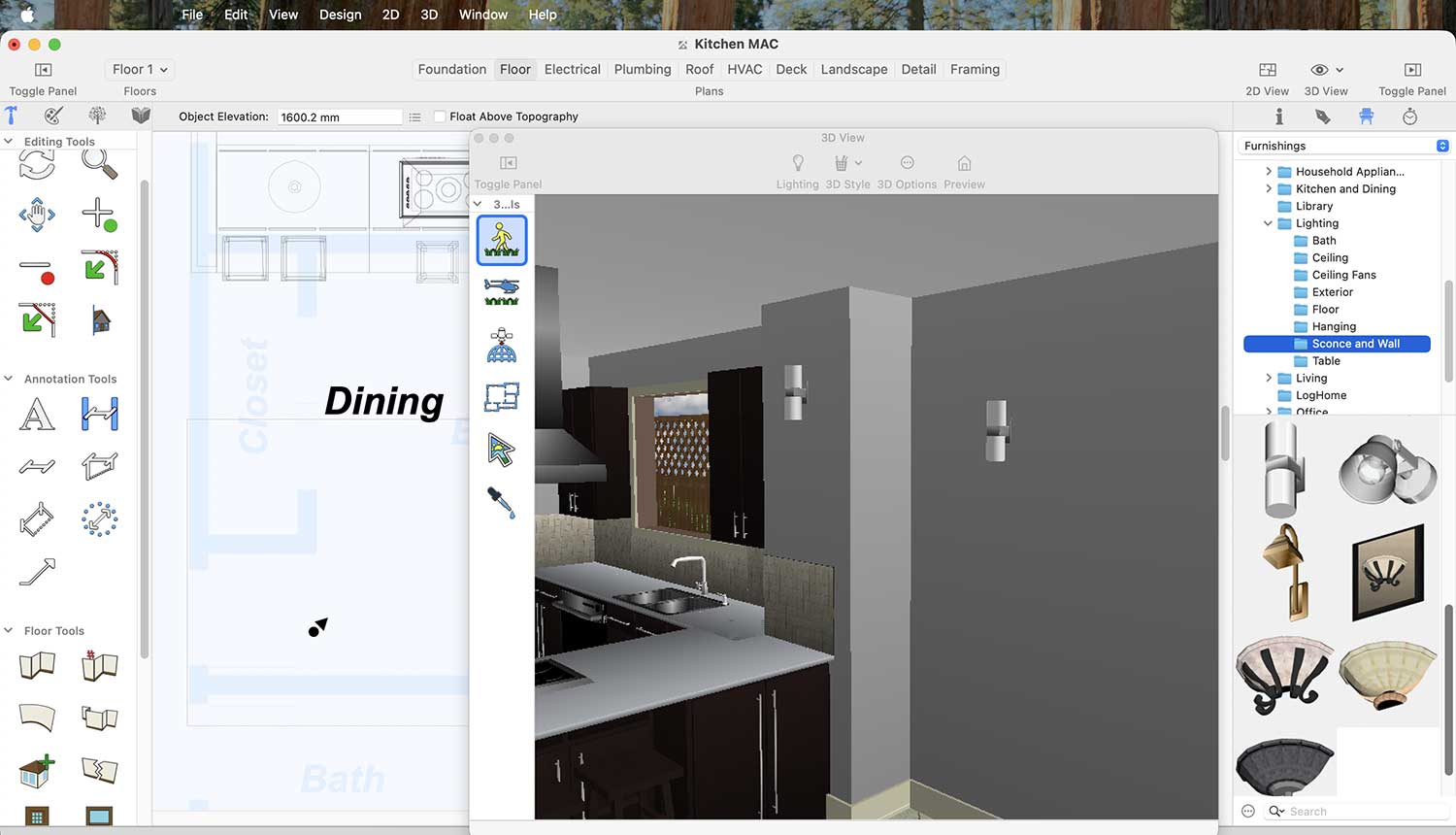
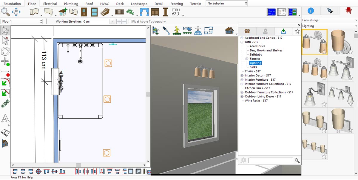
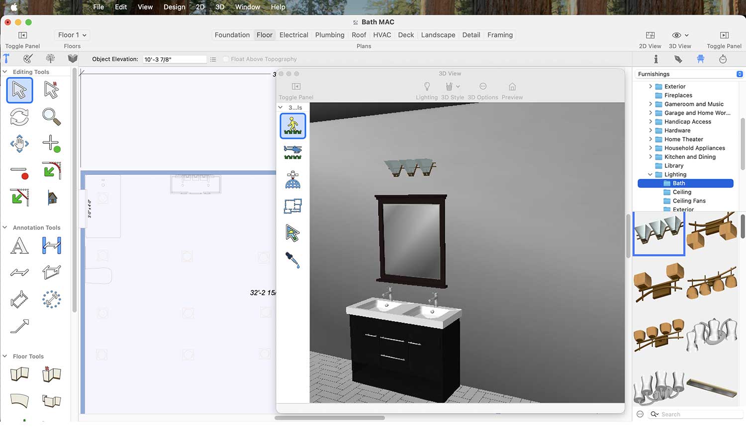
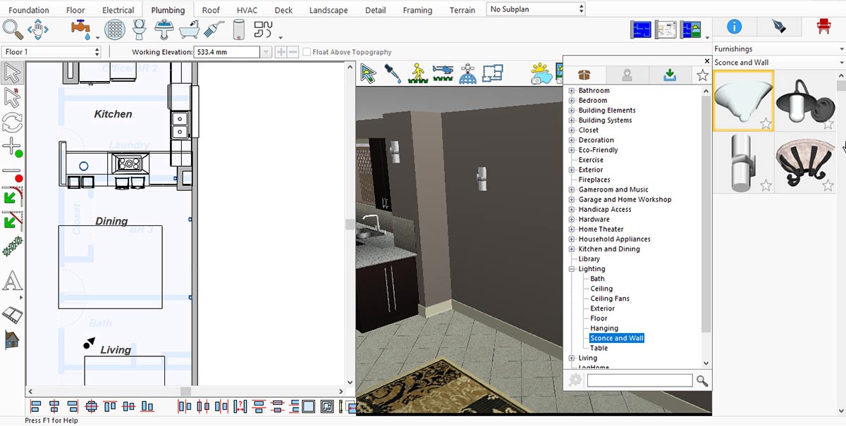
Similarly, Fancy lights also play an important role in a modern look to your Living Room. To please a Fancy light on wall go to Standard Library > Lighting > Sconce and Wall.
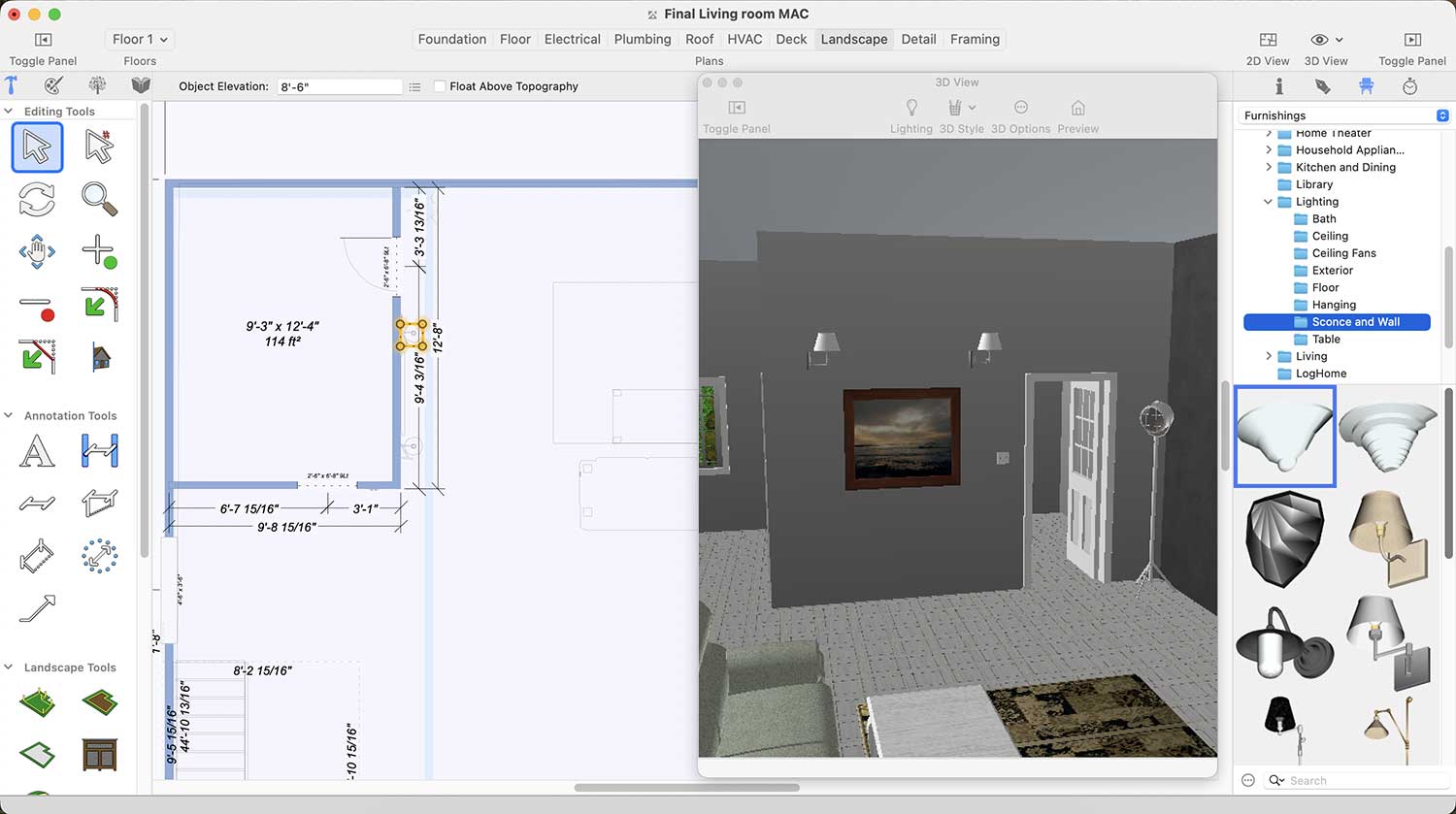
Wall Light Collection for Living room
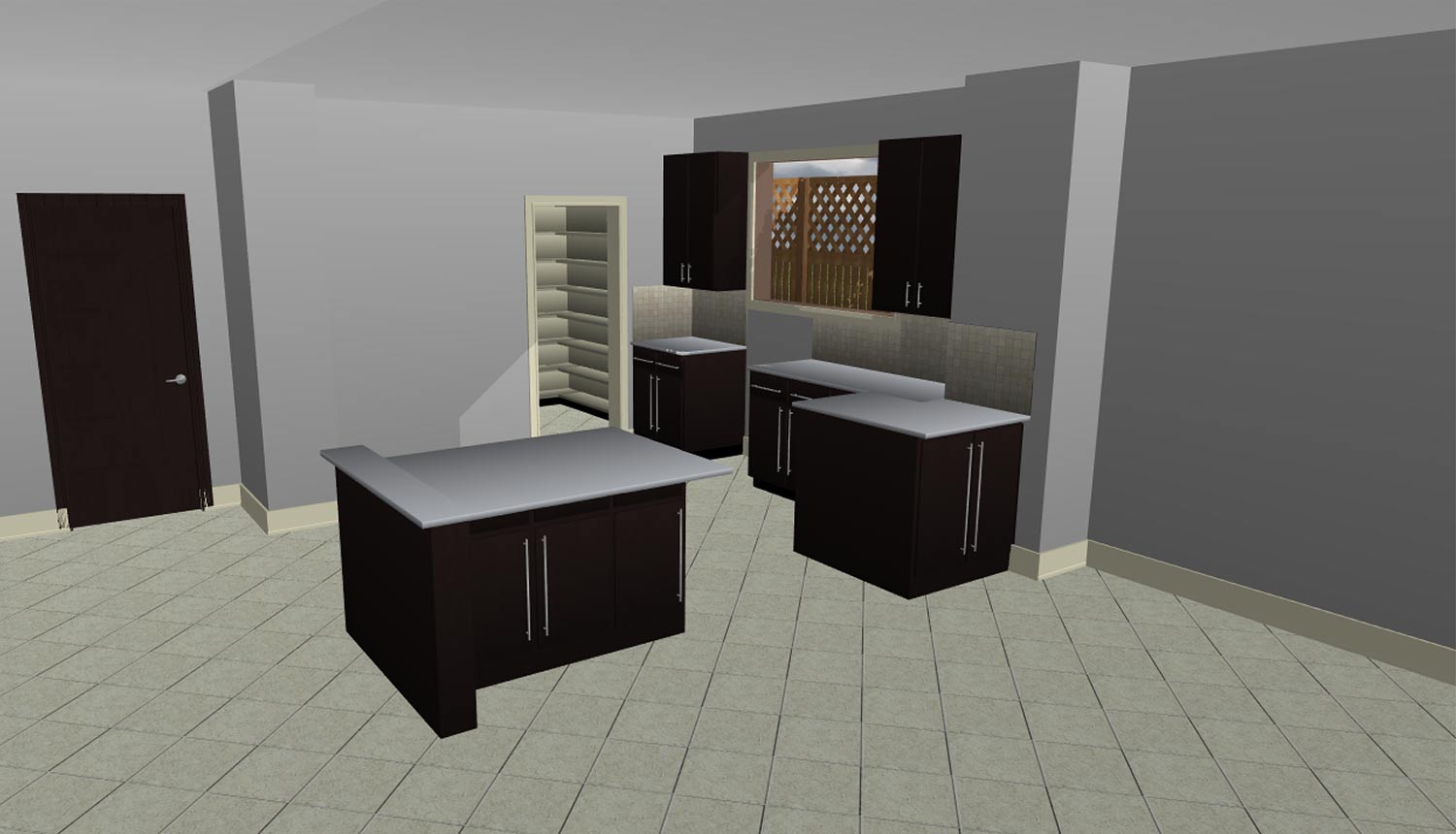
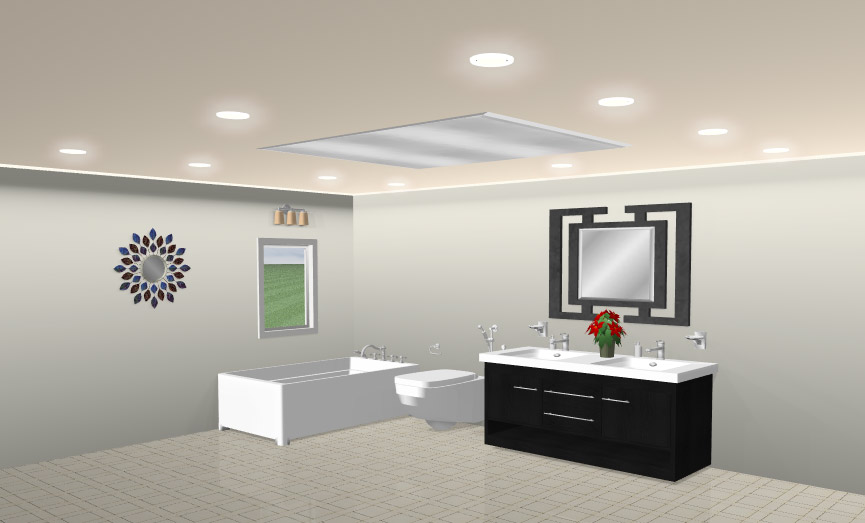
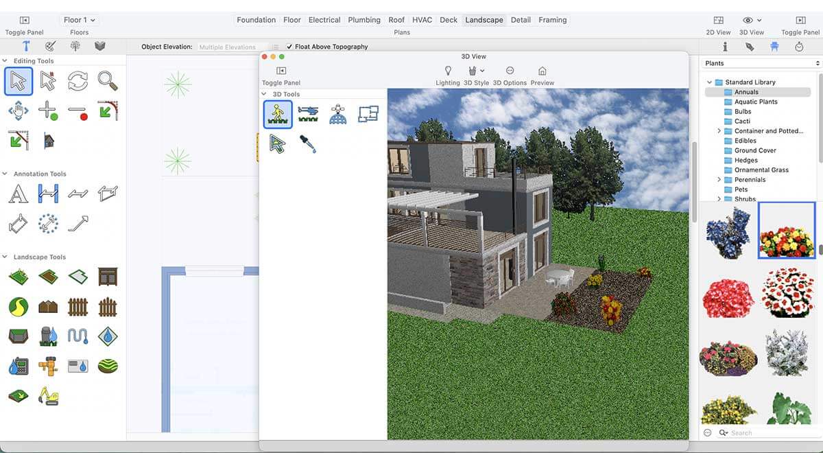
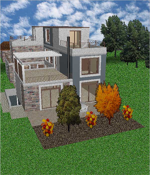
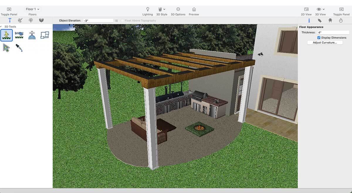
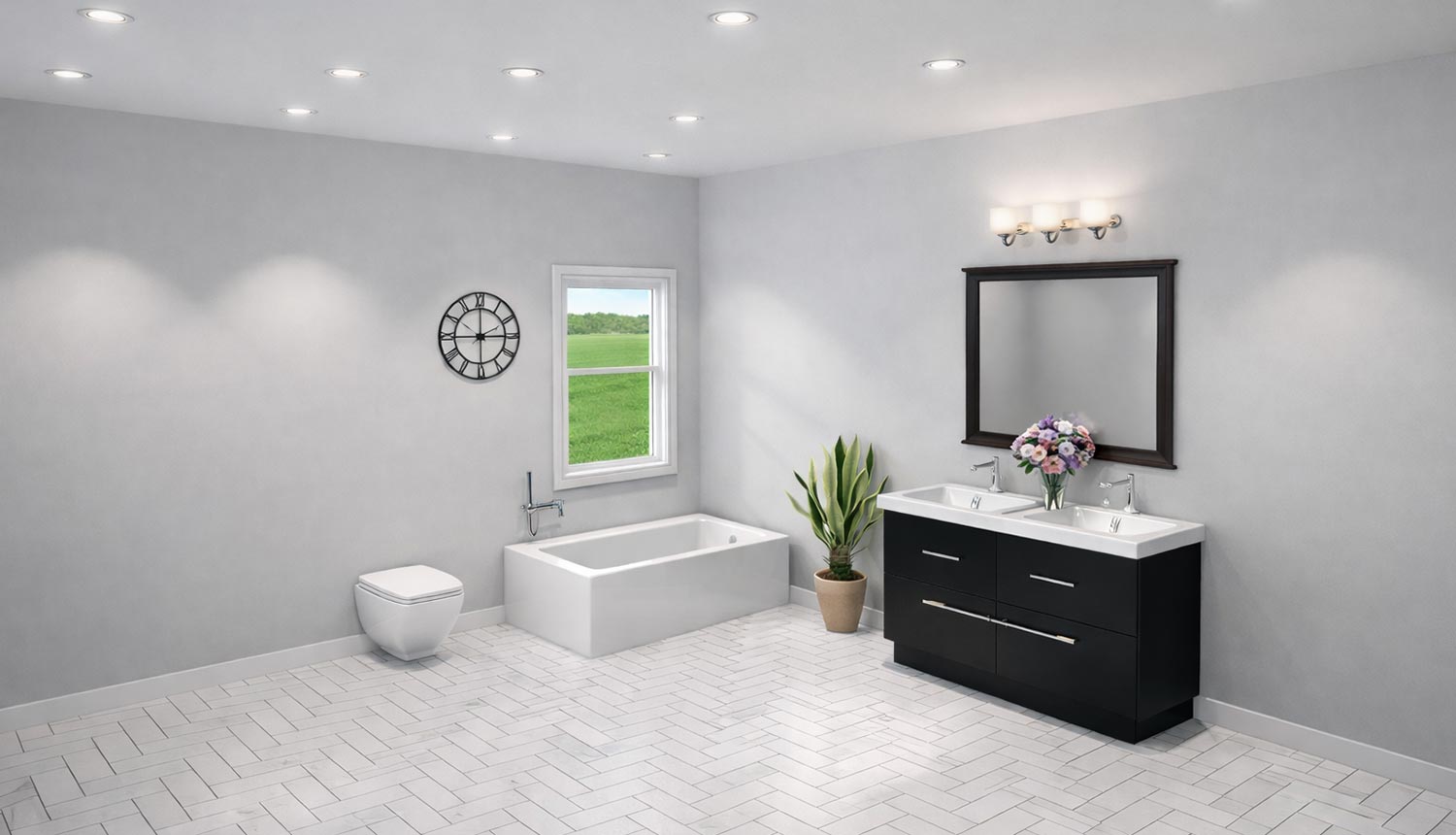
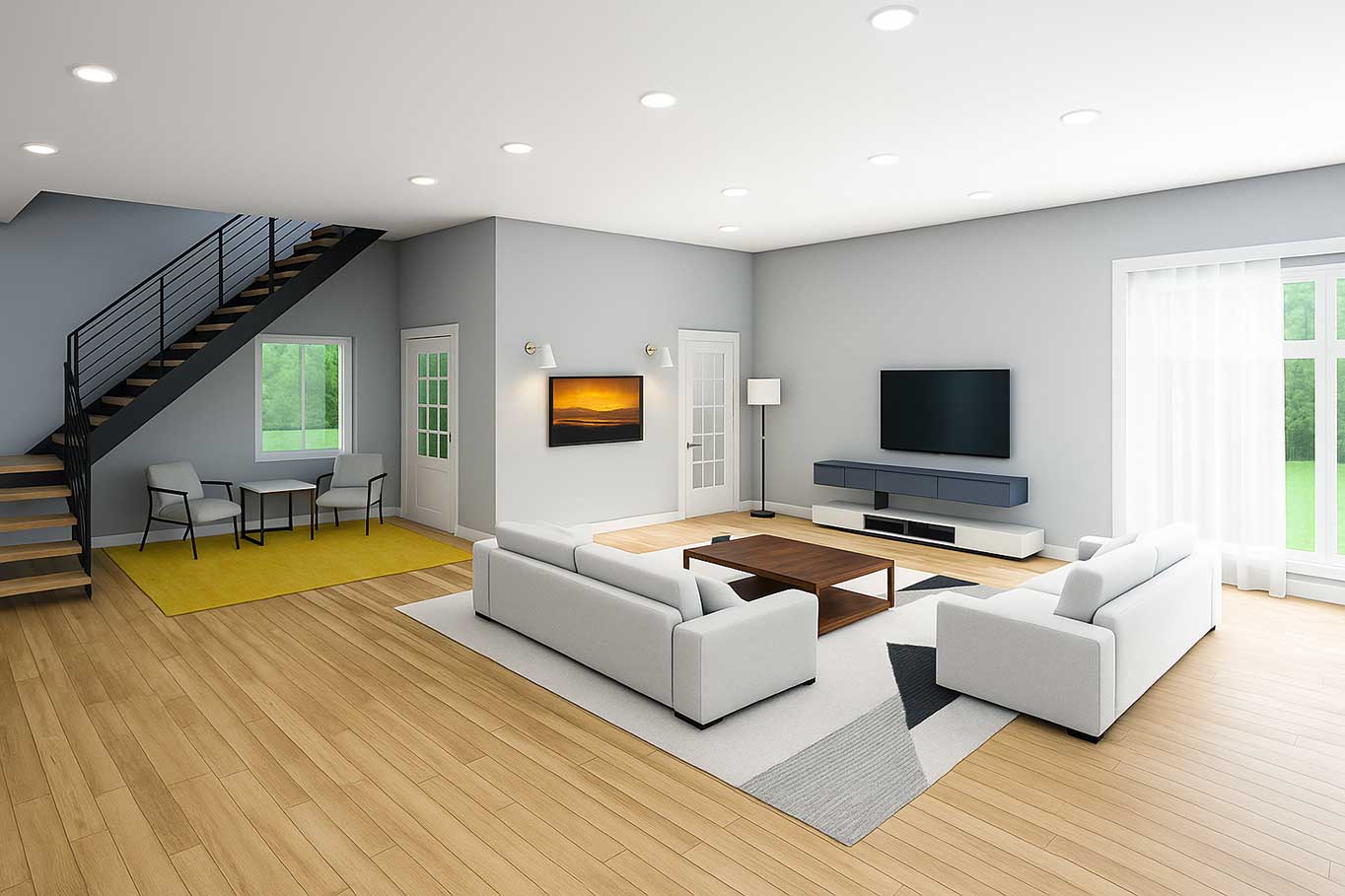
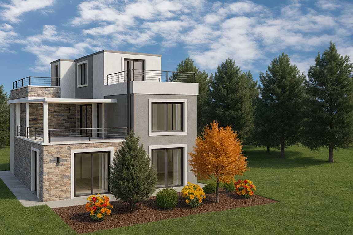
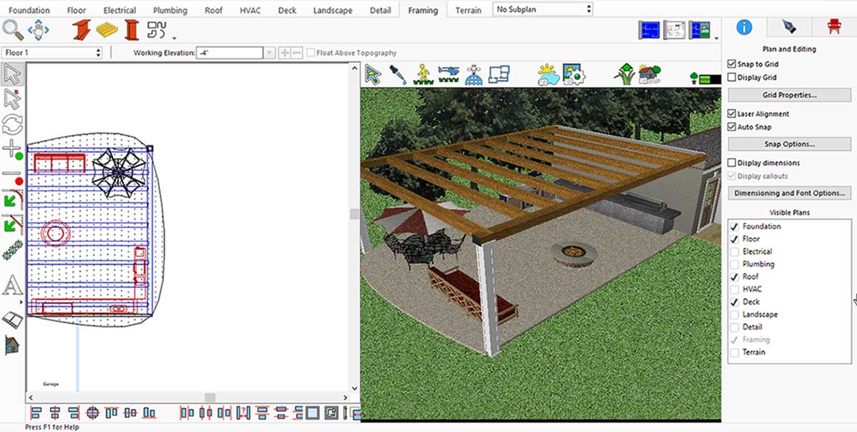
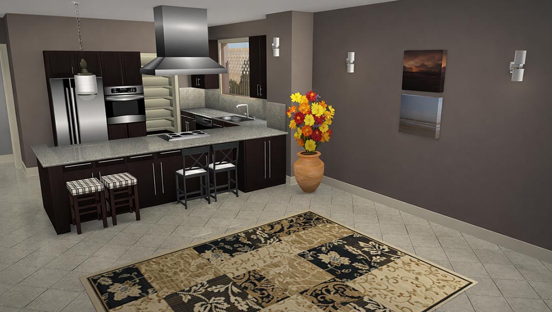
After placing all the accessories in the living room, you will need to render it to see the final results.
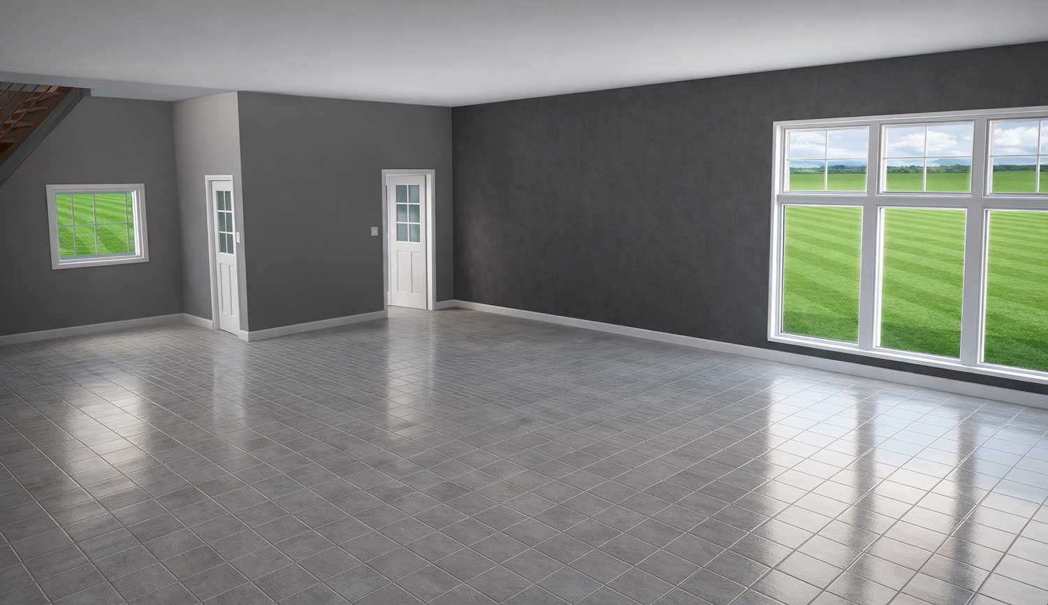
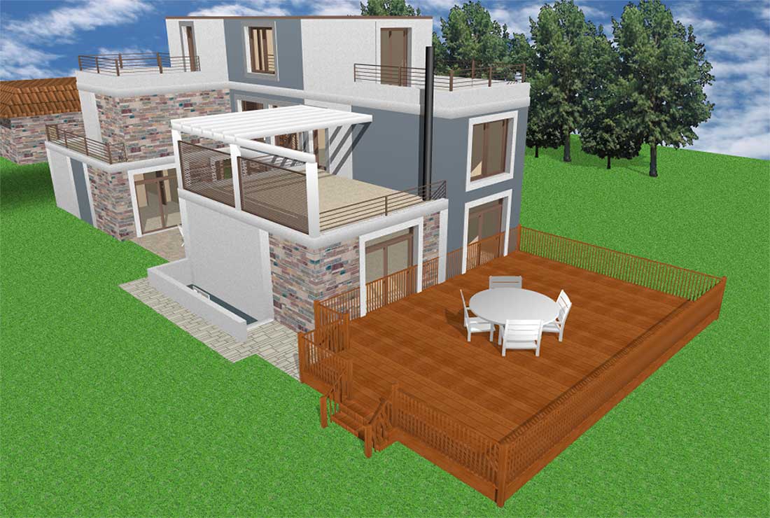
Before renovating the look of the Living room
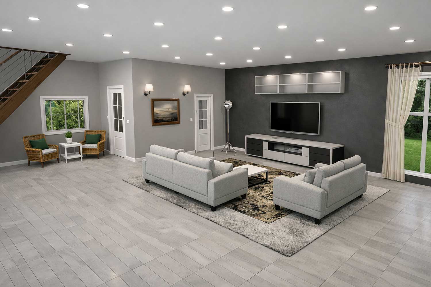
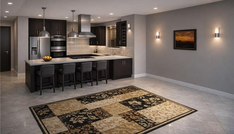
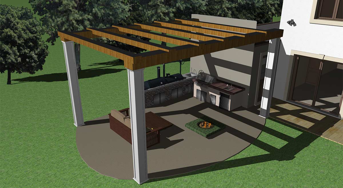
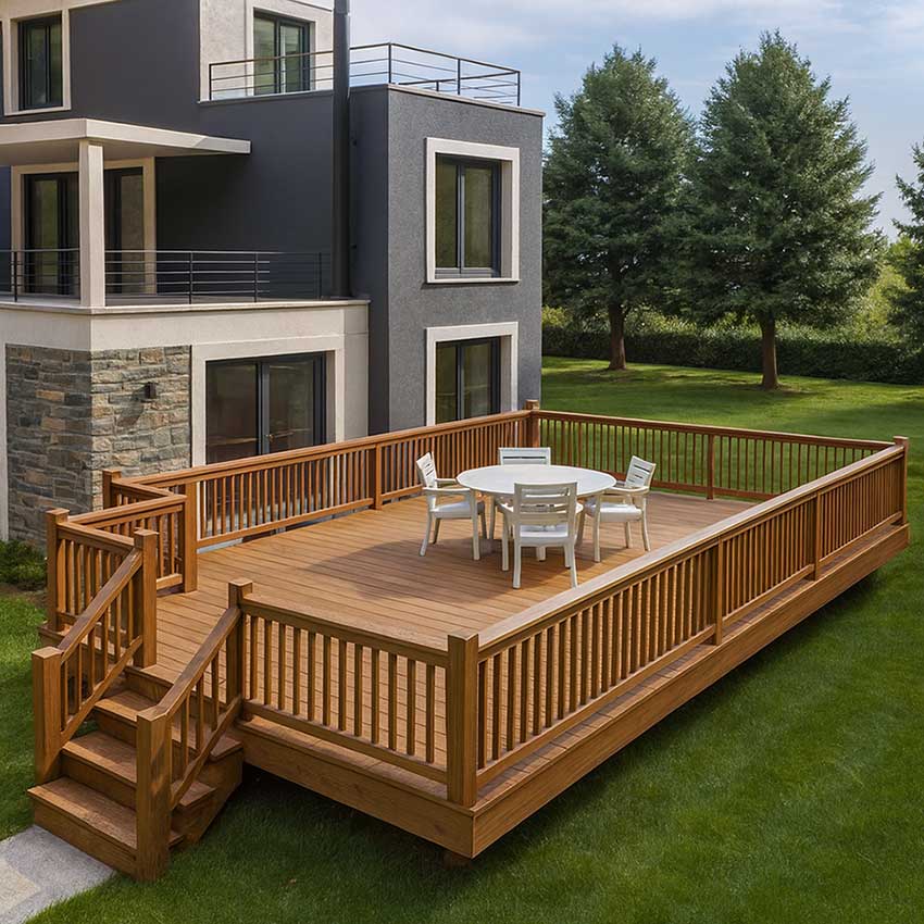
After renovating the look of the Living room
Designing a living space using the right tools and decorative elements makes the entire process creative, flexible, and enjoyable. From selecting furniture, carpets, doors, and windows to adding wall accessories, lighting, and modular storage, each element plays an important role in creating an elegant and attractive living area. The use of default and downloaded libraries provides a wide range of design options, making it easier to customize the space according to personal preferences. The final rendered view clearly shows how thoughtful selection and proper placement of accessories can completely transform a living space into a well-balanced, stylish, and welcoming environment.
Now it’s your turn: to redesign your space and enjoy the beauty of your efforts every day.